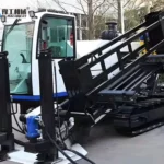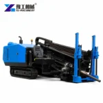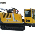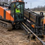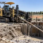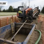
A horizontal drill rig installs a guided underground bore by combining a drill string, a rotating powerhead and controlled axial movement. In horizontal directional drilling, the pilot establishes the route, reaming enlarges it where required, and pullback installs the product pipe or conduit. The work depends on tool control and ground response as well as the rig’s available force.
The YG-320 and YG-320A provide a useful equipment comparison because their published force and torque figures are the same while their push-pull mechanisms differ. Understanding the drilling process explains what those ratings do—and why no single row guarantees a successful crossing.
How A Horizontal Drill Rig Steers, Reams And Pulls Back
In a conventional steerable soil-tool arrangement, the pilot head has a geometry that produces a directional bias when advanced in a controlled orientation. Rotation distributes that bias around the axis to support straighter progress; controlled orientation and advance produce steering. This describes a drilling principle, not a promise that every ground condition can be steered with the same head.
The location system supplies information about the downhole assembly. Tool position and orientation need to be interpreted against the designed route, the system’s limitations and possible interference. Tracking does not reveal every existing underground service or replace the required utility investigation. The route must be established and managed under a competent drilling plan before the machine’s steering function is used.
After the pilot, a reamer may enlarge the passage for the intended installation. The reamer cuts and disturbs a larger volume of material, changing torque and fluid demand. A staged enlargement may be necessary according to the ground and design. A large tool inside the rig’s published diameter range is not automatically suitable for a single pass.
Pullback introduces the product pipe or conduit into the load path. The drill string supplies the pulling action, while a suitable swivel arrangement limits unwanted torque transfer to the product. Pipe pull limits, bending, connections and the bore condition must remain within the installation design. Maximum rig pull is not permission to impose that force on any pipe.
For a horizontal drill rig, these stages have different controlling conditions. Pilot accuracy, reaming performance and product installation should not be collapsed into one advertised bore-length or production figure. The utility directional drilling article gives related crossing context.
Pilot drilling, reaming and pipe pullback place different demands on the equipment.
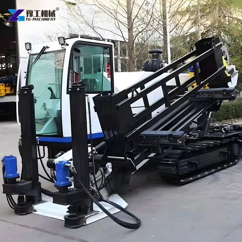
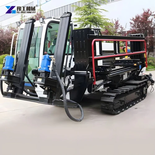
YG-320 And YG-320A Horizontal Drill Rig Specifications
These figures compare two configurations in the same YG horizontal directional drilling family. They describe equipment limits and arrangements, not a guaranteed achievable crossing in every formation.
| Parameter | YG-320 | YG-320A |
| Engine rated power | 140 / 160 kW | 160 kW |
| Push-pull mechanism | Cylinder | Motor |
| Maximum drag / feed force | 320 / 320 kN | 320 / 320 kN |
| Maximum powerhead torque | 12,000 N·m | 12,000 N·m |
| Powerhead speed | 0–140 r/min | 0–140 r/min |
| Powerhead moving speed | 20 m/min | 20 m/min |
| Maximum reaming diameter | 800 mm | 800 mm |
| Single drill rod length | 3 m | 3 m |
| Drill pipe diameter | 73 mm | 73 mm |
| Maximum mud flow | 320 L/min | 320 L/min |
| Maximum mud pressure | 80 bar | 80 bar |
| Machine weight | 11,500 kg | 11,200 kg |
| Length × width × height | 7,100 × 2,250 × 2,450 mm | 7,662 × 2,162 × 2,450 mm |
The feed-drive label explains how the carriage is actuated. It does not alone establish higher drilling speed, finer control or automatic rod loading. Both machines list the same maximum powerhead moving speed. The proposed configuration and operating controls need to be identified separately from assumptions about what a motor or cylinder arrangement implies.
Torque, rotation speed and axial force are also different capabilities. Hydraulic power must serve the working functions under their actual load. Separate maximum rows should not be interpreted as a simultaneous operating point at the tool. A demanding reaming pass may place a different balance of loads on the machine from pilot drilling or unloaded carriage travel.
The 800 mm maximum reaming figure is not a universal hole-completion promise. Ground, reamer type, drill-string capacity and fluid transport remain relevant. Similarly, carriage speed cannot be divided into crossing length to estimate job time: rod connections, steering, tool changes and separate passes occupy real parts of the operation.
Compare the named YG model and feed arrangement, not only the maximum force.
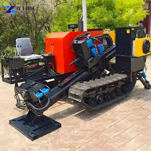
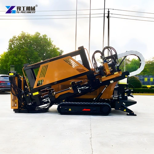
Horizontal Drill Rig Rods, Tooling And Guidance Equipment
Drill rods transmit axial and rotary loads while carrying drilling fluid internally. Their diameter, connection design and permitted bending characteristics need to suit the rig and bore. A nominally similar rod is not automatically interchangeable. The approved connection and make-up requirements protect the load path through every section of the string.
The 3 m rod length listed for both YG configurations affects handling and the repeated working cycle. Adding or removing a section involves alignment and connection work, not merely carriage motion. The offered rod-handling and breakout arrangement should be identified clearly; a generic rig photograph does not establish automatic handling equipment.
Bending limits require particular attention in directional work. The planned curvature must respect the permitted rod and product limits rather than assume a steering tool can create any desired turn. Repeated excessive bending can damage the string even where no immediate failure is visible. A sharper correction is not necessarily a better correction if it moves the equipment outside its permitted geometry.
Pilot tools and reamers need to suit the formation. A soil steering head and a rock-capable drilling arrangement have different requirements. The presence of torque on the main machine does not prove that the offered tooling can penetrate and steer through competent rock. Any specialized rock system needs to be part of the confirmed compatible configuration.
The drilling system also needs appropriate guidance and trained interpretation of its readings. Locator and transmitter compatibility, interference conditions and tracking method should be considered alongside the drill rather than added as an afterthought. These systems assist the operation but do not replace service locating, exposure or other controls required by the drilling plan.
Ground And Drilling Fluid Around A Horizontal Drill Rig
Drilling fluid performs several functions: it supports the selected cutting process, helps transport disturbed material and affects friction and bore conditions. Its mixture needs to suit the ground and equipment. A pump’s maximum flow and pressure do not identify the right formulation, mixing arrangement or return-handling system.
Clay can interact with water and drilling additives differently from granular ground. Sticky or reactive material may accumulate around a tool or change the character of the returning slurry. Sand and gravel introduce other challenges, including bore stability and particle transport. Competent rock requires tooling suited to that cutting task; it is not simply soil drilling with more pressure.
The fluid sent down the string needs a controlled return path. Restrictions, loss into the ground or an unintended release can change the operation even while the pump continues running. A rising gauge reading should not automatically trigger more pressure. The contractor needs the monitoring and response plan appropriate to the bore and surrounding environment.
Reaming increases the amount of material disturbed. Advancing faster than the fluid and tool arrangement can manage does not necessarily improve completed output. It can create poor transport conditions and additional load. The operating combination needs to reflect actual returns, ground response and the selected system’s limits rather than the fastest available carriage setting.
For a complete HDD package, mixing, supply, containment and any recovery equipment must be identified separately. The listed onboard pump does not prove that those items are included. The directional drilling equipment price discussion provides related scope context without replacing the technical match between fluid, tool and ground.
Tooling and fluid management should address the actual formations along the route.
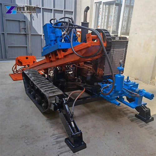
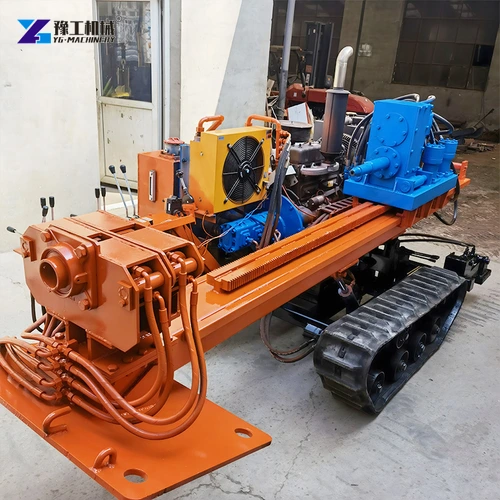
Horizontal Drill Rig Inspection And Controlled Completion
Wear and damage in the string can affect every bore stage. Rod connections, tooling, clamps and accessible hydraulic components need the inspections required by their instructions. Damaged threads or abnormal connection behaviour should not be ignored because the next rod can still be fitted. The condition of the load path is more important than maintaining an uninterrupted handling rhythm.
The machine must be positioned and restrained through its approved arrangement. Axial forces generated in drilling and pullback need a suitable reaction path into the supported installation. Tracks and machine mass alone do not establish that path. Ground condition and the actual anchoring or restraint system remain part of the setup.
Moving rods, clamps, rotating assemblies and pressurized lines create hazards during normal operation and maintenance. The prescribed exclusion, isolation and depressurization procedures apply before access or adjustments. A stalled tool or stopped carriage should not be treated as proof that all stored energy has disappeared.
Completion also includes assessing the installed product under the project requirements and managing remaining drilling fluid and spoil. Reaching the exit point is not the only acceptance condition. A horizontal drill rig supplies the mechanical operation, but the finished crossing still needs the inspection and records appropriate to the installation.
The useful product comparison joins these functions together: guided cutting, compatible rods, controlled feed and rotation, suitable fluid management and maintained equipment. Equal force figures leave meaningful configuration differences open, while a larger maximum rating does not remove the need for that complete drilling system.
Specify the rig, compatible string, guidance and supporting equipment as one working system.
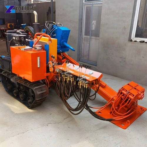
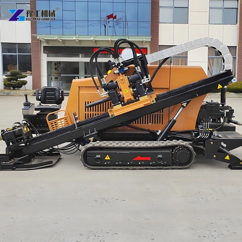
Horizontal Drill Rig FAQs
In a conventional steerable soil-tool arrangement, rotation tends to distribute the directional bias, while controlled orientation and advance provide steering. Other tooling and ground conditions can require different systems.
No. The product, connections, swivel, string and installation design have their own limits. Rig capacity must not be treated as the allowable load of every component.
No. Tool selection, ground, fluid conditions and the complete load path affect feasibility. The figure describes a published machine boundary rather than every completed bore.
Not by itself. The supply scope must identify mixing, supply, containment and any return-processing equipment separately.
No. Guidance assists tracking the drilling assembly. Existing services and other hazards require the investigation and controls established by the drilling plan and applicable requirements.
Tell us the intended utility installation and ground conditions to discuss a suitable machine, drill string and supporting system.