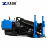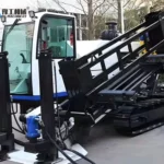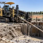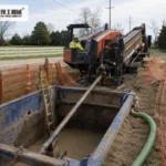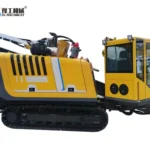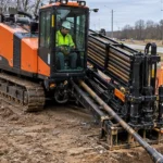
Utility directional drilling installs pipes or conduits beneath roads, landscaped areas and other obstacles with limited surface excavation. The project begins with the utility route, existing-service survey, ground information, product-pipe size, crossing length and allowable bend radius. The HDD machine is selected only after those constraints define thrust, pullback, torque, drill rods, reaming and mud requirements.
YG models from YG-160A through YG-320A provide different pull/feed forces, torque, reaming diameters and mud capacities. The model table supports preliminary screening; it does not replace a bore plan or prove that the largest listed reamer fits every soil and product pipe. A useful inquiry includes route drawings, utility records, ground evidence and the full installation target.
Related selection pages: horizontal directional drilling equipment, directional drilling process for utility crossings, HDD drilling fluid planning, and HDD pullback force calculation.
Share the route profile, product-pipe size, ground information and launch/reception footprints so the rig, rod string, reaming plan and mud package can be screened together.


Define the Utility Directional Drilling Crossing
Mark the launch and reception areas, crossing length, required cover, entry and exit positions, road or obstacle width and the route available for the product pipe. Record access for the rig, mud system, rods, reamers, excavator and transport. Tight urban sites may be controlled by setup space even when the bore length is moderate.
Complete the required utility locating and permits before design. Existing electric, gas, water, communication and drainage services affect the bore path and monitoring plan. Define exclusion zones and potholing or exposure requirements under the local project method. The machine operator should receive an approved path, not be expected to resolve conflicts while drilling.


Utility Directional Drilling Machine Parameters
| Model | Engine | Pull / feed | Torque | Max reaming | Rod | Max mud flow | Mud pressure | Weight |
| YG-160A | 100 kW | 160 / 100 kN | 5000 N·m | 600 mm | 3 m × 60 mm | 160 L/min | 100 bar | 6700 kg |
| YG-180 | 97 kW | 180 / 180 kN | 6000 N·m | 600 mm | 3 m × 60 mm | 250 L/min | 80 bar | 8500 kg |
| YG-280 | 160 kW | 280 / 280 kN | 10000 N·m | 750 mm | 3 m × 73 mm | 320 L/min | 80 bar | 12500 kg |
| YG-320 | 140 / 160 kW | 320 / 320 kN | 12000 N·m | 800 mm | 3 m × 73 mm | 320 L/min | 80 bar | 11500 kg |
| YG-320A | 160 kW | 320 / 320 kN | 12000 N·m | 800 mm | 3 m × 73 mm | 320 L/min | 80 bar | 11200 kg |
Use pull/feed force and torque to shortlist a rig against the crossing plan. Maximum reaming diameter, rod dimensions and mud limits are model values—not proof that every maximum can be used together in any ground—so check the full tool string and bore profile.
Plan Drill Rods, Bore Geometry and Pullback
Match the drill rods and tool string to the selected HDD model, bore geometry and ground. Rod length and diameter affect the drill-side footprint, handling cycle and steering response. Check the product pipe’s allowable bend radius so the planned profile can be built without forcing sharp corrections.
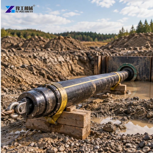
Estimate pullback from the pipe, bore length, reamed diameter, ground, mud, buoyancy control, friction and route geometry. Machine pullback is one selection input, not permission to operate at the maximum. Record the planned swivel, reamer, product connection and monitoring method.

Control HDD Mud Flow and Ground Response
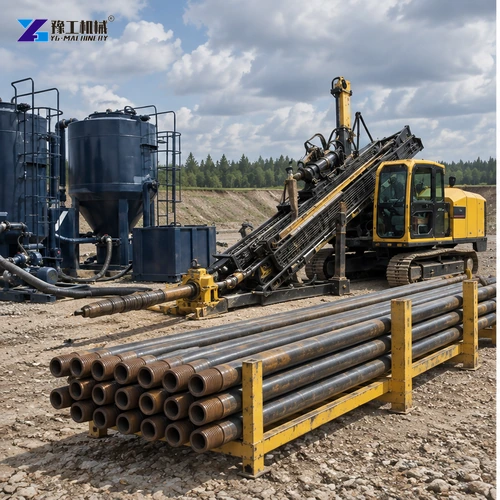
Select mud equipment from the model table together with the ground and tooling plan. Maximum machine values are not automatic operating settings for every drilling stage. The working program must support cuttings transport while protecting the bore and surrounding ground.
Build the fluid program around soil or rock, bore diameter, filtration and disposal. Monitor returns, pressure, loss zones and inadvertent-release risk. Sand, clay, fill and mixed ground may require different fluid properties and reaming decisions. Keep records by bore stage so the crew can adjust from evidence rather than relying on a single recipe.
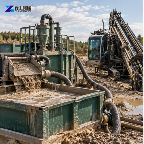
Mark the rig, mud system, rod handling, pipe string and returns area against the bore plan before delivery; this shows whether the work zone fits without blocking the crossing or public access.
Arrange the Utility HDD Work Zone
Separate the rig, rod handling, mud mixing and recycling, pipe string, lifting equipment and public route. Confirm ground bearing, anchoring, overhead clearance, lighting and drainage. Delivery and setup planning must use the exact machine model selected in the parameter table.
Create communication and stop-work rules between the drill operator, locator, mud technician, pipe-side crew and site supervisor. Track steering data and compare it with the approved path. The work zone must remain functional through pilot drilling, reaming and pullback.
Prepare a Utility Directional Drilling Proposal
Send route length and profile, product-pipe material and diameter, allowable bend radius, required cover, ground report, existing utilities, launch and exit space, reaming plan, target schedule, destination and local compliance requirements. Include photographs or drawings showing road edges, structures, overhead limits and pipe-string space.
Ask YG to identify the model, rods, drill head, reamers, swivel, mud pump and mixing package, locator compatibility, tools, spares, manuals, packing and test scope. Keep project engineering and machine supply responsibilities explicit. This allows the buyer to compare complete HDD packages while preserving the engineer’s control of the actual crossing design.
Ask the offer to identify the rig, rod string, reamers and mud equipment separately; the listed scope should make clear which parts match the crossing and which remain the contractor's responsibility.
Utility Directional Drilling for Road and Pipe Crossings FAQ
Provide the approved route, pipe size and material, ground, length, bend radius, reaming plan, pullback estimate and site access.
No. Ground, bore stability, tooling, product pipe and pullback requirements must be evaluated together.
YG-280, YG-320 and YG-320A list 3 m × 73 mm drill rods.
Fluid supports the bore and transports cuttings; flow, pressure and properties must match the ground and each drilling stage.
Request a Utility Directional Drilling Quote
For a utility directional drilling package, provide crossing length and depth, pipe diameter and material, ground conditions, bore path, entry and exit footprints, and room for the drill string. These conditions determine the rig, rods, reamer and mud-handling package.