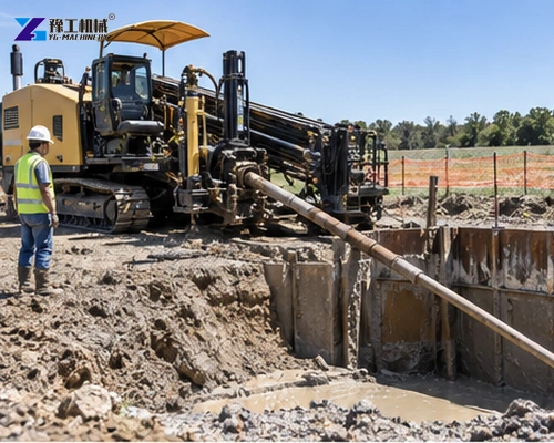
An HDD pullback force calculation estimates the resistance expected while a product pipe travels through a reamed bore. It is not the same as choosing the rig’s maximum pull rating. The design must account for pipe properties, bore geometry, buoyancy, friction, fluid behavior and uncertainty, while keeping pipe stress and tooling loads within allowable limits.
This guide explains the calculation workflow buyers should complete before comparing horizontal directional drills. It is a screening and procurement framework, not a substitute for project engineering or the applicable design standard.
Build The Bore And Pipe Data Set
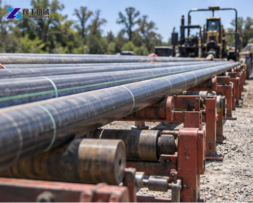
Start with pipe material, outside diameter, wall thickness, length, unit weight, allowable tensile load and minimum bend radius. Add pull head, swivel, reamer and any internal fluid. For welded pipe strings, include the complete installed length and the arrangement of rollers or supports on the entry side.
Define entry and exit angles, depth, horizontal alignment, curve radii and reamed diameter. Divide the path into sections because submerged weight, contact force and curvature differ along the bore. A single average friction value can conceal the section that controls the peak load.
Separate Weight, Buoyancy And Friction
The pipe’s effective submerged weight depends on displaced drilling fluid and on whether the pipe is empty, water-filled or intentionally ballasted. Buoyancy may reduce straight-section contact but can increase normal force at the crown of a curved bore. State the assumed internal and external fluids explicitly.
Friction acts along the pipe-bore interface and depends on contact force, lubrication, soil, filter cake and bore condition. Use the project’s approved coefficient range and calculate sensitivity rather than presenting one optimistic value. Surface drag before the pipe enters the bore must also be included.
Curvature And Capstan Effects
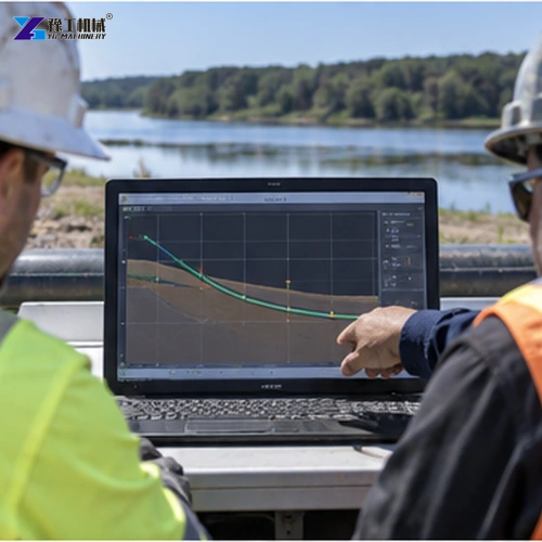
At a curve, tension on one side can increase relative to the other as the pipe bears against the bore. The calculation should follow the specified method for capstan or curve resistance and use the actual change in direction. Tighter bends generally increase contact and may also consume the pipe’s bending capacity.
Check the product pipe independently for combined pulling and bending stress. A rig capable of delivering high force can still damage the pipe if the allowable installation load is lower. The HDD process guide shows where pilot-bore accuracy and reaming decisions enter the final pullback condition.
Drilling Fluid And Bore Condition
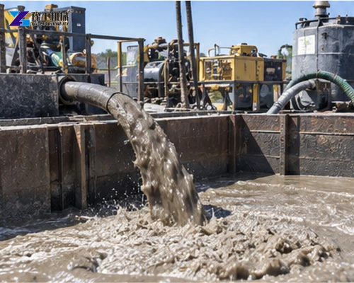
Drilling fluid transports cuttings, stabilizes the bore and lubricates pullback. Lost returns, swelling formations, accumulated cuttings or an undersized ream can raise resistance beyond the desk estimate. The plan should define fluid properties, circulation volume, return monitoring and response limits.
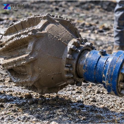
Reaming passes should create a clean, stable annulus suitable for the pipe and ground. Oversizing without control can increase fluid demand or instability, while inadequate clearance increases contact. Record reamer type, diameter, rotation, flow and observed returns for each pass.
Published HDD Rig Range For Screening
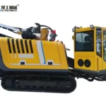
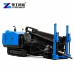
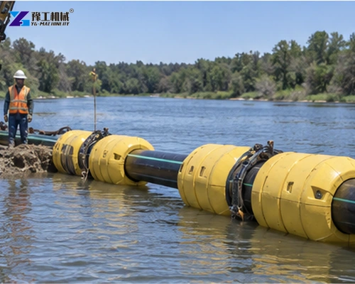
YG horizontal directional drilling equipment provides the following reference range. Compare calculated required force with the machine’s rated pull/feed force only after applying the project’s required margin and checking torque, rods and tooling.
| Model | Max pull/feed | Powerhead torque | Max reaming diameter | Drill rod |
| YG-160A | 160/100 kN | 5,000 N·m | 600 mm | 3 m × 60 mm |
| YG-180 | 180/180 kN | 6,000 N·m | 600 mm | 3 m × 60 mm |
| YG-280 | 280/280 kN | 10,000 N·m | 750 mm | 3 m × 73 mm |
| YG-320 | 320/320 kN | 12,000 N·m | 800 mm | 3 m × 73 mm |
| YG-320A | 320/320 kN | 12,000 N·m | 800 mm | 3 m × 73 mm |
Rated force alone does not prove suitability. Confirm machine anchoring, rod tensile capacity, swivel and pull-head ratings, torque for the reamer, mud-pump capacity and the expected steering response in the project ground.
Monitor The Pull And Use Stop Criteria
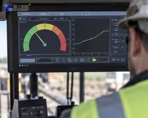
Record actual pull force, torque, rotation, fluid pressure, returns and pipe movement during installation. Compare the trend with predicted values. A rising load can indicate cuttings buildup, poor lubrication, curve contact or an obstruction and should trigger the project’s response procedure before a limit is exceeded.
Set stop criteria for rig capacity, product-pipe allowable load, tooling rating, fluid loss and abnormal movement. Preserve the load record with the bore log so future crossings can use evidence rather than a generic percentage allowance.
Calculation Report And Procurement Handoff
A useful calculation report lists every input, unit, source and assumption. Include pipe properties, bore stations, bend radii, fluid density, friction range, surface support and tooling weights. Show intermediate results by bore section so reviewers can identify whether a curve, straight section or entry-side drag controls the peak.
Run cases for expected, favorable and adverse conditions. Sensitivity is especially important where ground data is limited or fluid returns may be difficult. The purpose is not to add an arbitrary large machine margin; it is to understand which uncertainty could push the installation beyond pipe, tooling or rig limits.
The drilling proposal should connect the calculation to construction controls. State pilot tolerances, ream sequence, final clearance, cleaning passes, fluid properties, return monitoring, pipe support, ballast and planned pulling speed. A force number without a bore-conditioning plan is not a complete basis for procurement.
Compare every load path component: product pipe, pull head, swivel, reamer, drill rods, breakout system, carriage and anchor. Use allowable working loads under the project method, not merely ultimate ratings. Check torque and mud capacity alongside pull force because a rig can have adequate pull but insufficient reaming performance.
Before quotation, send the bore profile and calculation workbook together with the geotechnical summary, pipe specification, utility constraints and destination. YG can then compare suitable rigs and tooling, identify missing inputs and avoid selecting a machine from pipe diameter alone.
Common Reasons The Estimate And Field Load Differ
The installed bore may deviate from the design profile. Small steering corrections can create extra curvature and contact, especially where survey intervals are long. Use the as-drilled pilot data and reaming records to update the pullback review before attaching the product pipe.
Cuttings beds increase drag when circulation is inadequate or the bore is left open too long. Track pumped and returned volumes, fluid properties and cleaning passes. A clean-looking return at one location does not prove the complete annulus is clear.
Pipe handling on the surface can add avoidable resistance. Provide enough rollers, align them with the entry path and control side loading. For long strings, temperature expansion and site grade may also change the support forces before the pipe reaches the bore.
During pullback, compare load change with rig position and bore stations. This correlation helps distinguish normal curve resistance from a developing obstruction. Stop early enough to investigate; using reserve force without diagnosis can consume the margin intended for uncertainty.
Worked Calculation Review Without False Precision
Before approving the calculation, check units and sign conventions. Pipe weight may be stated per meter while a model expects total weight, and fluid density may appear in several unit systems. A transparent worksheet should make conversions visible and prevent a plausible-looking result built from incompatible inputs.
Review the path station by station. Confirm where the pipe is supported on the surface, where it enters fluid, where curvature changes and where the longest contact develops. Compare the calculated peak location with field experience and the planned rig position. Unexpected geometry often matters more than extra decimal places.
Apply the project’s specified safety or contingency factors at the correct point in the method. Do not multiply several conservative allowances without understanding their basis, and do not remove margin simply to fit a smaller rig. State separately the predicted operating range, design requirement and allowable limits.
Have the drilling contractor, pipe designer and equipment supplier review the same report. Their responsibilities differ, but all need consistent assumptions. Resolve discrepancies before procurement so rig selection, reaming plan, pipe stress and tooling ratings do not rely on different versions of the bore.
HDD Pullback Force FAQ
No. Pullback force also includes buoyancy, friction, curvature, surface drag and project-specific bore conditions.
No. Product pipe, rods, swivel, pull head and other tooling may have lower allowable loads, and an engineering margin is required.
Friction and bore condition are uncertain. Sensitivity analysis shows whether the selected system remains suitable under less favorable conditions.
Provide bore profile, ground information, pipe details, ream plan, fluid assumptions, calculated force range, tooling requirements, utilities and destination.