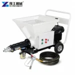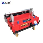
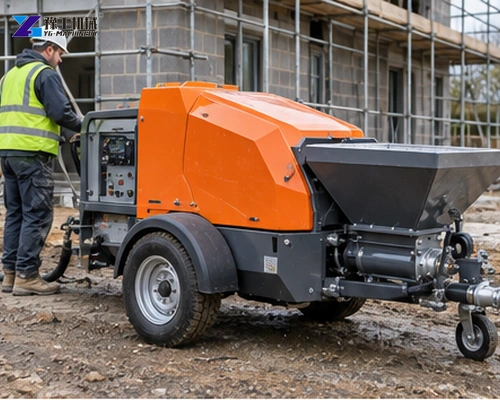
A render spraying machine can improve wall coverage only when the material, pump, hose and spray air work as one system. Buyers who compare machines only by motor power often overlook aggregate limits, hose losses and the finish method that determine whether the wall receives a steady, workable layer.
This guide connects material preparation with machine selection and site organization. It is aimed at contractors using cement render, premixed mortar or compatible plaster products. A representative material trial remains the safest way to confirm flow, spray pattern and cleaning procedure.
Start With The Approved Render Mix
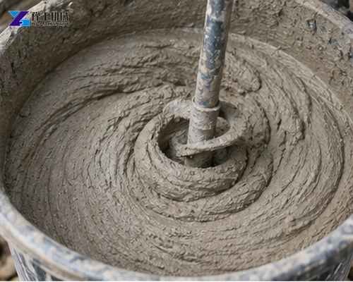
Record binder, sand grading, maximum particle size, additives, water ratio and required working time. Remove oversize particles and foreign material before they enter the hopper. A pump may pass an occasional large grain yet still suffer repeated blockage when the aggregate distribution is unsuitable.
The mix must stay pumpable without becoming so wet that it sags on the wall. Confirm whether mixing is included or separate, how batches are timed and how consistency is checked. Changes in sand moisture can alter the required water even when the nominal recipe stays the same.
Match Pump Output To Crew And Wall Area
Higher nominal output is useful only when the crew can place, level and finish the material before it sets. Estimate square meters per hour from layer thickness and material density, then include interruptions for repositioning, corners, scaffolding and batch changes.
Plan a controllable range rather than one maximum rate. The operator should be able to reduce flow for edges and detailed work without unstable pulsation. Compare the mortar pump machine when the project emphasizes conveying distance or feeding a separate spray system.
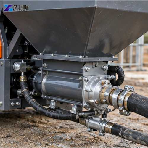
Published Render Spraying Machine Parameters
The current mortar spraying machine range provides several reference configurations. Confirm the selected motor, voltage and particle limit against the actual product before ordering.
| Model | Capacity | Pressure | Main motor | Particle size | Air consumption |
| YG-311 | 3 m³/h | 3 MPa | 4 kW | Below 4 mm | 0.3 m³/min |
| YG-318 | 3–5 m³/h | 3 MPa | 7.5 kW | Below 8 mm | 0.3 m³/min |
| YG-711 | 4–6 m³/h | 3 MPa | 7.5 kW | Below 8 mm | 0.3 m³/min |
Capacity values describe machine throughput under suitable conditions, not finished wall area. The practical result depends on layer thickness, rebound, stoppages and the number of finishers. Ask the supplier to state whether the compressor, mixer, hoses and gun are included.
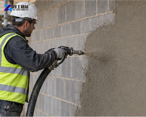
Hose Route And Compressor Demand
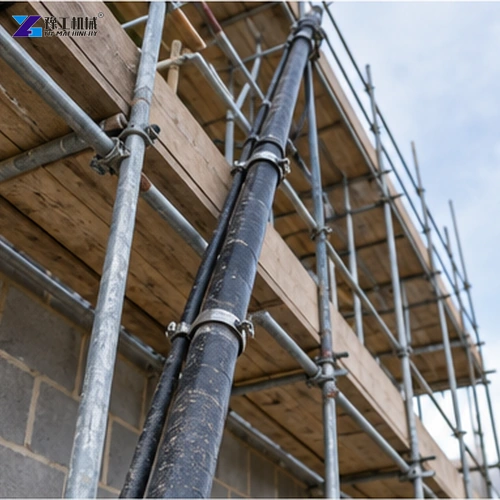
Long hoses, small diameters, tight bends and vertical lifts increase resistance. Draw the normal route from machine to gun, including scaffold levels and relocation points. Support the hose so its weight does not pull the operator or kink at couplings.
Compressed air shapes and accelerates the material at the nozzle; it is different from the pump’s material pressure. Confirm delivered airflow at the required pressure, not receiver size alone. Provide filtration, drains and a safe hose connection arrangement.
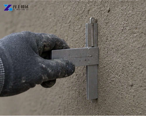
Control Layer Thickness And Finish
Hold the gun at a consistent angle and distance while moving at a steady rate. Build the specified thickness in suitable passes rather than flooding one area. Corners, reveals and changes in suction often need a slower rate and closer coordination between gun operator and pump operator.
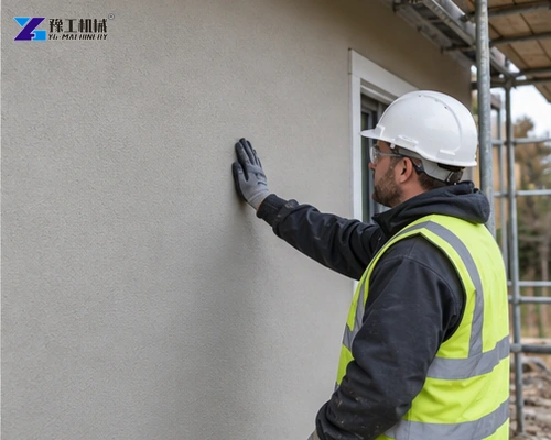
Define acceptance before the trial: coverage, thickness range, flatness, texture, rebound and curing method. Measure representative areas after finishing. A smooth pump trace is valuable, but the accepted product is the completed wall, not simply material leaving the hose.
CHECK MY WALL FINISH REQUIREMENT
Cleaning, Blockage Control And Daily Workflow
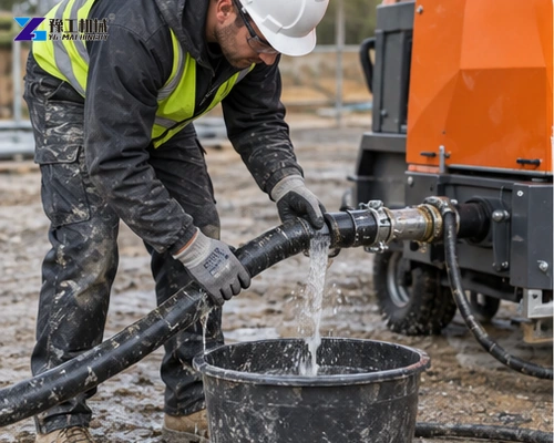
Plan cleaning before material enters the machine. The crew needs water, waste collection, safe depressurization and access to hopper, pump, hose and nozzle. Do not open a coupling until stored pressure is released. Hardened residue reduces capacity and creates unpredictable blockages on the next shift.
Change one variable at a time when spray quality deteriorates. Check material consistency, aggregate, obstruction, hose condition, nozzle wear and airflow before raising pressure. Record the accepted recipe and settings so another crew can repeat the result.
CONFIRM MY RENDER SPRAY PACKAGE
Site Trial, Scope And Operating Cost
A representative trial should use the intended render, normal hose length and production nozzle. Record mixing water, batch time, material temperature, pump setting, air pressure, spray distance, layer thickness, rebound and finished texture. Run long enough to include a normal pause and restart, because many blockages occur during interruptions rather than continuous spraying.
Clarify the supplied scope: mixer, hopper, pump, compressor, air hose, material hose, gun, nozzles, cleaning tools, cable and spare wear parts. If the buyer supplies a compressor, confirm delivered airflow at pressure and connector compatibility. If material arrives prebagged, verify local bag weight and mixing equipment.
Estimate cost per finished square meter, not per cubic meter pumped. Include material waste, rebound, crew size, scaffolding moves, masking, finishing, cleaning water, disposal, energy and downtime. A high-output pump does not lower cost when finishers cannot keep pace or when overspray creates repair work.
Organize the work zone so dry material, mixing, pumping, hose routing, spraying and waste collection do not interfere. Protect couplings from traffic, provide lighting at the wall and keep a clear route for communication between pump and gun operators. Define an emergency stop signal before spraying begins.
Send YG the material technical sheet, sample or recipe, maximum grain, planned thickness and texture, daily wall area, hose length, vertical rise, power, compressor data and destination. Those details allow the machine and auxiliary package to be checked against the actual finishing task.
Variables To Control During Production
Temperature, wind and substrate suction change how quickly render loses water. Prepare the wall according to the material supplier’s method and coordinate spraying with curing. A machine cannot compensate for an excessively dry, dirty or moving substrate.
Nozzle selection affects spray pattern and air demand. Keep approved nozzle sizes available and replace worn parts before the operator compensates with pressure. Mark hoses by diameter and service condition so an unsuitable replacement is not introduced during a busy shift.
Crew balance should be reviewed after the first working area. If finishers fall behind, reduce pump rate or add labor rather than building excessive wet material on the wall. If the gun waits repeatedly for batches, improve mixing and feeding before blaming pump capacity.
Keep a daily record of material batches, water, machine settings, hose route, weather, output and defects. These records make later bids more accurate and help separate equipment issues from mix or site variation.
Pre-Delivery Trial And Site Handover
Inspect the machine against the approved scope and motor data. Confirm hopper guards, emergency stop, pressure indication, hose connections, cleaning tools and supplied nozzle sizes. Check that the electrical configuration matches the destination and that cables and plugs suit the planned protection system.
Use representative render for the factory or site trial. Operate across a useful output range, include the planned hose length and observe restart after a normal pause. Record mixture, water addition, nozzle, air supply, pump setting, achieved thickness and finish. Preserve photographs and an accepted sample area.
Train both pump and gun operators. The pump operator must recognize starvation, excessive pressure and unsafe hose behavior; the gun operator must control distance, angle and overlap. Both need a clear stop signal and a depressurization procedure before any coupling or blockage is opened.
Agree on wear parts and cleaning responsibilities at handover. Keep spare seals, stator or pump components, nozzles and approved lubricant where required. A written end-of-shift routine prevents hardened material from turning an otherwise suitable sprayer into a recurring maintenance problem.
Render Spraying Machine FAQ
No. The product must be approved for pumping and spraying, and its particle size, working time and water demand must fit the machine.
No. Excess pressure can increase rebound and wear. Stable material flow, correct air and operator technique are more important.
Convert material flow using layer thickness and density, then allow for interruptions, rebound, edges, relocation and finishing capacity.
Send material data, sample or recipe, required thickness and texture, wall area, hose route, lift height, utilities, daily target and destination.