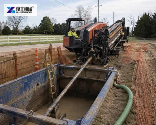
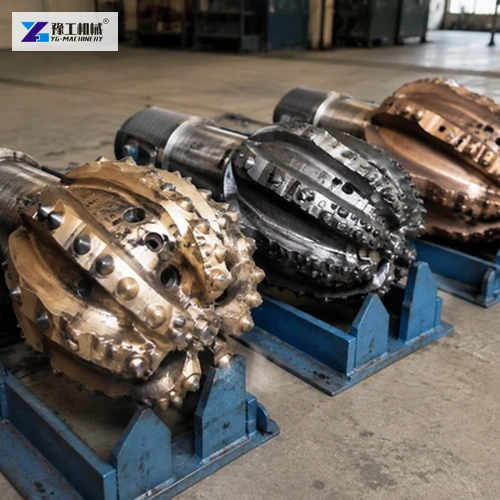
HDD reamers enlarge a pilot bore so the product pipe can be installed with controlled clearance and a stable pullback path. Choosing a tool only from the final pipe diameter ignores the ground, bore curvature, drilling-fluid transport, rig torque and pullback limits. A successful plan connects each reaming stage to the evidence collected during the pilot bore.
This buyer guide explains the information a contractor should send when matching reamers and a directional drilling rig. Tooling remains geology-specific, and the final bore program must be approved by qualified project personnel.
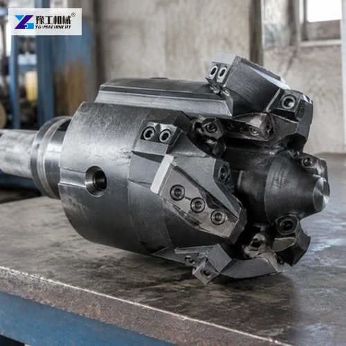
Begin With Product Pipe And Bore Geometry
Record product pipe outside diameter, material, joint type, minimum bend radius and allowable pullback force. Include the proposed bore profile, entry and exit geometry, length, depth and utility clearances. The required enlarged bore is a project decision; there is no universal multiplier that is suitable for every pipe and ground condition.
The annular space must support pullback and fluid return without creating an unnecessarily large unstable opening. Bundled conduits, casing, external joints or protective coatings change the effective envelope. Confirm the largest installed feature rather than using nominal pipe size alone.
Directional Drilling Rig Parameters Set Boundaries
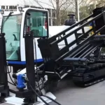
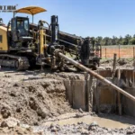
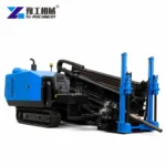
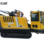
The horizontal directional drilling equipment page publishes these reference models. Maximum reaming diameter is an equipment comparison boundary, not confirmation that a particular diameter is achievable in every geology or bore length.
| Model | Pull/feed force | Powerhead torque | Published max reaming diameter | Drill rod | Mud flow | Mud pressure |
| YG160A | 160/100 kN | 5000 N·m | 600 mm | 3 m × 60 mm | 160 L/min | 100 bar |
| YG180 | 180/180 kN | 6000 N·m | 600 mm | 3 m × 60 mm | 250 L/min | 80 bar |
| YG280 | 280/280 kN | 10000 N·m | 750 mm | 3 m × 73 mm | 320 L/min | 80 bar |
| YG320 | 320/320 kN | 12000 N·m | 800 mm | 3 m × 73 mm | 320 L/min | 80 bar |
| YG320A | 320/320 kN | 12000 N·m | 800 mm | 3 m × 73 mm | 320 L/min | 80 bar |
Use the actual rig condition and installed components. Torque at the tool, available pullback, rod capacity, pump output and mixing system all influence the practical stage. Check which values are maximum ratings and which can be sustained in the intended work.
Send product pipe details, bore profile and ground information so YG can compare the rig envelope and tooling questions for your crossing.
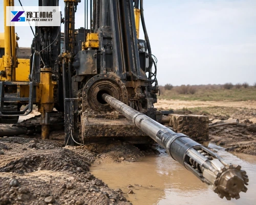
Ground Conditions Determine Reamer Type
Soil identification should come from investigation and pilot-bore response. Cohesive soil, loose granular material, cobbles and competent rock require different cutting and fluid behavior. Mixed ground may demand more than one tool type or a revised sequence because a reamer efficient in clay can behave poorly when cutters encounter rock.
Record penetration rate, steering response, torque, thrust and returns during the pilot bore. Note zones of loss, heave or obstruction. These observations help confirm whether the anticipated ground model is accurate and whether the planned first enlargement remains appropriate.
Keep samples and location references where the project procedure requires them. A change observed over a short distance may control the cutter choice for the whole pass because the tool must cross that zone safely in both directions. Update the ground profile rather than treating the pilot log as an isolated drilling record.
Cutting Structure And Gauge Protection
Inspect cutter type, mounting, body diameter and wear protection. In abrasive formations, gauge wear can reduce the effective hole size before a long pass is complete. Replaceable cutters and clear inspection criteria help the crew decide whether a tool can safely make another pass.
Fluid Passages And Spoil Transport
Nozzles and passages must distribute drilling fluid where cutting and transport require it. More flow is not automatically better; the mixing, pumping, returns containment and cleaning system must handle the planned circulation. Monitor pressure and returns for evidence of blockage or loss.
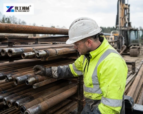
Select Reaming Stages From Evidence
The difference between consecutive tool diameters must remain manageable for the rig, rods, ground and fluid system. A single large jump may overload tooling or leave poor spoil transport. Too many unnecessary stages add time, wear and repeated disturbance. Develop a provisional sequence, then define decision points for changing it.
For each stage, state tool type, nominal diameter, travel direction, expected torque and pull, fluid plan and acceptance condition. After the pass, inspect the tool and review recorded data before approving the next diameter. The HDD process guide provides the broader sequence around pilot drilling, enlargement and product installation.
Confirm the reamer-to-rod and swivel connections as part of the stage sheet. Every adapter introduces a rated component and a possible wear point. Measure the complete assembly length where exit-side space is restricted, and plan safe tooling changes without improvising lifting points.
If a stage departs from the expected torque, pull or return behavior, pause at the agreed threshold. Review bore progress and tool condition before choosing a smaller increment, a different cutter structure or additional conditioning pass.
Provide pilot-bore logs and the proposed diameter sequence when you need a stage-by-stage tooling and rig review.
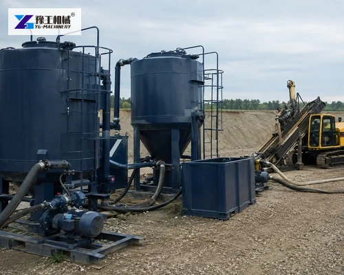
Drilling Fluid Capacity Must Match The Stage
Estimate the excavated volume for planning, then adjust for actual returns and formation behavior. Tank capacity, mixing rate, pump delivery, solids control and disposal route must keep pace with the selected tool. A rig’s pump rating alone does not prove that the site can prepare and recover enough conditioned fluid.
Define properties and field checks appropriate to the project. Track make-up volume, returns, losses and cleaning performance. If returns decline, do not continue automatically; investigate the bore condition and follow the approved response plan.
Pullback Is Part Of Reamer Selection
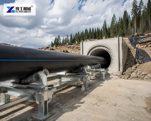
The final pass must leave a path compatible with pipe bend limits and allowable pull force. Plan rollers, pipe support, swivel, pulling head and connection lengths. Include product pipe, tooling and fluid drag when comparing the rig’s capacity and rod limits.
Monitor pullback load against the planned threshold. An oversized bore does not guarantee low force if cuttings settle, the path is tight or the pipe enters at a poor angle. Coordinate the final conditioning pass and pipe preparation so the opening is not left unsupported longer than necessary.
Share allowable pipe pull, bend radius, rig data and final tool arrangement so the complete pullback package can be checked.
Tool Inspection And Field Records
Inspect threads, cutters, jets, body, swivel and connections before use. Confirm every component rating covers the intended torque, thrust and pull. Establish exclusion zones and use approved handling equipment; reamers are heavy and must not be manually positioned beneath suspended loads.
During each pass record time, distance, rotation, thrust or pull, fluid pressure, flow, returns and observed ground changes. After recovery, measure wear and retained diameter where the procedure requires it. These records support the next-stage decision and explain deviations from the plan.
Send the crossing package and pilot-bore evidence when the project is ready for a directional drilling rig and tooling proposal.
HDD Reamer Buyer FAQ
No. Ground, joint envelope, bore geometry, annular clearance, rig limits and drilling-fluid transport also control the choice.
No. The required bore and stages should be engineered for the specific product, ground and installation method.
No. It is a comparison boundary. Bore length, geology, tooling, rods, fluid system and machine condition can impose lower practical limits.
Record tool, diameter, distance, rotation, thrust or pull, fluid flow and pressure, returns, time, wear and any observed ground change.