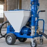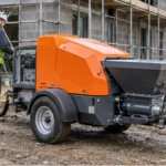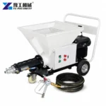
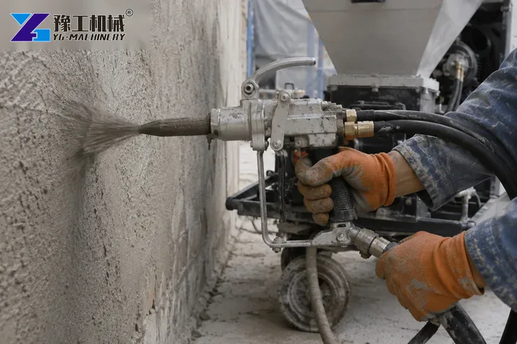
An air compressor for a mortar sprayer supplies the air that shapes and accelerates material at the spray gun. It does not create the material pressure that moves mortar through the delivery hose. Confusing those two systems leads buyers to compare the sprayer’s 3 MPa maximum material pressure with a compressor air-pressure rating, even though the values describe different circuits and cannot be substituted for each other.
The correct purchasing task is to confirm the gun and nozzle demand at a stated working pressure, then make sure the compressor can deliver that air through the real hose for the required duty cycle. Material, aggregate, hose length, lift height, spray texture, climate and site power all influence the final test. The YG mortar sprayer machine page provides the connected pump range; this guide focuses only on its compressed-air package.
Compressed Air Functions At The Mortar Spray Gun
The material pump meters mortar to the gun. Compressed air meets that stream at the nozzle, breaks it into a controlled pattern and provides the velocity needed to place it on the surface. Too little delivered air can create a heavy, pulsing stream, poor distribution and higher rebound from large slugs. Excess air can increase dust, rebound, noise and material separation without improving the accepted finish.
Required air depends on the installed gun, air cap, nozzle diameter and desired texture. Obtain the gun manufacturer’s demand at its stated inlet pressure and identify whether the figure is free-air delivery, displacement or another rating basis. Do not select from receiver size or motor horsepower alone. The comparison must use delivered flow at pressure under the same reference conditions.
Data Required Before Compressor Sizing
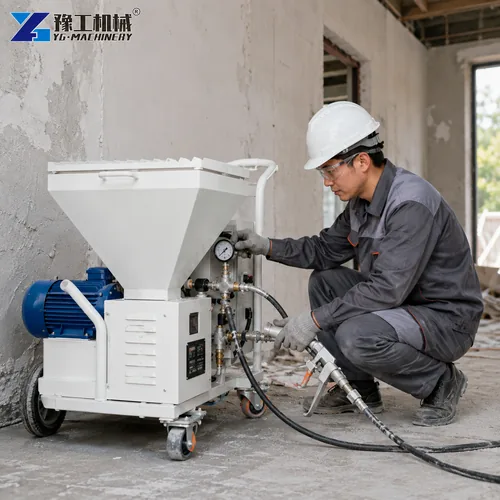
Record mortar type, approved mix, maximum aggregate, consistency, additives, expected coating thickness and finish. Add the sprayer model, material output, nozzle and air-cap part numbers, material-hose diameter, total length, vertical rise, number of hose joints and planned crew pattern. State whether the gun sprays continuously or pauses while the wall is leveled and the hopper is refilled.
Site information includes voltage, phase, frequency, available current, generator capacity, altitude, ambient temperature, ventilation, noise restrictions, access and maximum distance from compressor to gun. If several air tools share the supply, list their simultaneous demand and minimum working pressure. A vague request for a “large compressor” prevents the supplier from checking voltage, cable, protection, hose and duty cycle as one system.
Comparing Required And Delivered Air
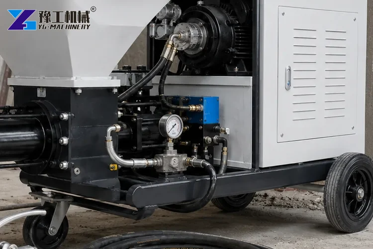
Start with the gun’s required free-air delivery at the specified inlet pressure. Add only a documented allowance for leakage, wear and expected operating variation. Compare that requirement with the compressor’s continuous delivered-air curve at the same pressure, not its theoretical piston displacement or zero-pressure flow. Confirm whether the published rating already accounts for ambient reference conditions.
Pressure and flow are linked. A compressor may show sufficient flow at a lower pressure but fall short at the gun requirement. Ask for the duty rating and control method: start-stop, load-unload or variable-speed behavior changes how the unit responds to a spraying cycle. If data use different units, convert them explicitly and keep the original values in the proposal.
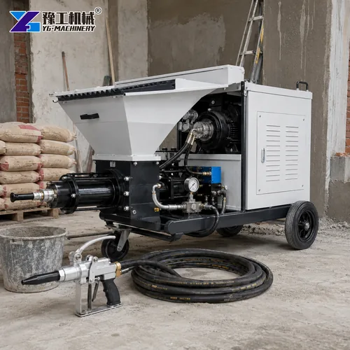
Air Hose Loss, Receiver Volume And Gun Performance
The compressor outlet is not the gun inlet. Long, narrow or kinked air hose; restrictive couplings; filters; regulators and water separators cause pressure drop. Lay out the full route, measure total equivalent length and size the hose for the required flow. Check pressure dynamically at the gun while spraying. A gauge at the receiver can look normal while the nozzle is starved.
A receiver buffers short peaks and reduces rapid cycling, but it does not create enough average air when the compressor is undersized. Size storage from the demand pattern, acceptable pressure band and compressor control, following the compressor supplier and local pressure-vessel rules. Drain management matters because moisture in the air line can disturb spraying and damage components. Provide accessible filtration and condensate handling.
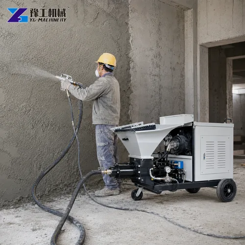
Mortar Sprayer Parameters For The Complete Package
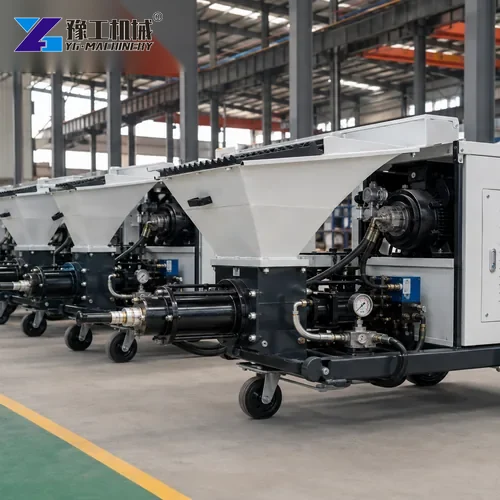
YG mortar sprayer configurations list maximum material pressure of 3 MPa, output of approximately 3–4 m²/h, main drive from 4–7.5 kW or 8/12 hp depending on model, maximum particle size from 4–8 mm, 32 mm material hose and 60–100 L hopper. Listed delivery ranges reach 30–50 m horizontally and 20–30 m vertically depending on model.
These values define the material side and production route. They do not declare a universal compressor flow or air pressure. A longer material route may change pump loading and crew rhythm, while a long air route creates its own pressure loss. Both circuits must be tested together with normal mortar. Model selection also checks available electrical capacity for the sprayer and compressor operating simultaneously.
| Sprayer input | Verified range | Compressor implication |
| Material pressure | Up to 3 MPa | Separate from spray-air pressure |
| Output | 3–4 m²/h | Helps define gun duty pattern |
| Maximum particle size | 4–8 mm | Influences nozzle and material flow |
| Material hose | 32 mm | Not the air-hose size |
| Delivery distance | 30–50 m H / 20–30 m V | Verify both material and air routes |
| Hopper | 60–100 L | Affects refill interruptions |
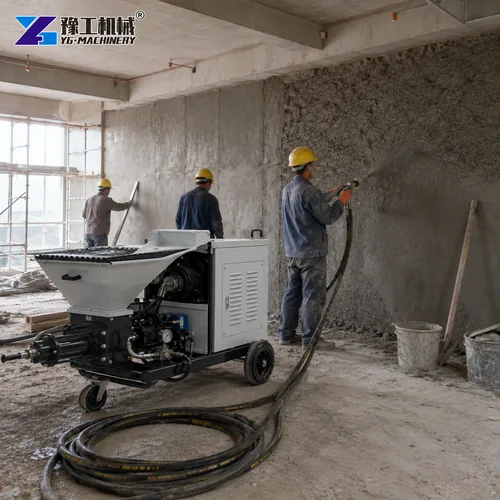
Site Power And Operating Conditions
For an electric compressor, confirm voltage, phase, frequency, starting method, cable length, protective devices and available current while the mortar pump also runs. A generator must handle starting and operating demand with suitable voltage and frequency control; nameplate kW addition alone may not describe motor starting. Diesel units add exhaust, fuel, fire and ventilation controls and may be unsuitable indoors.
Altitude and high ambient temperature can reduce compressor output and cooling margin. Dust can block coolers and filters. Position the unit on stable ground with service clearance and keep its intake away from spray mist and engine exhaust. Follow local rules for noise, pressure equipment, electrical work and condensate disposal. State any derating assumption in the quotation.
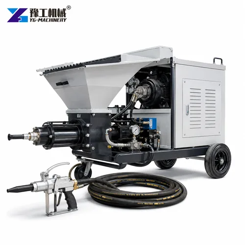
Compressor And Mortar Sprayer Commissioning
Use the approved mortar, maximum planned hose route, production nozzle and trained operator. Verify guards, couplings, whip checks where required, regulator, relief devices, filters and drains. Start with the supplier’s approved settings. Measure dynamic pressure at the gun, observe compressor loading and record spray pattern, rebound, material output, interruptions and temperatures over a representative working period.
Change one variable at a time. If the pattern is poor, check material consistency, aggregate, nozzle wear, obstruction, material flow and gun technique before raising air pressure. Confirm restart after normal pauses and show that cleaning can be completed before mortar sets. The acceptance record should identify gun, nozzle, hose, compressor, working settings, material and observed result.
Air Compressor For Mortar Sprayer FAQ
No. Material pressure moves mortar through its hose; compressor air atomizes the stream at the gun.
No. A receiver buffers peaks, but average delivered air must still meet continuous demand.
Check dynamic pressure at the gun while spraying, because hose and fittings cause losses after the receiver.
Send sprayer, gun, nozzle, material, duty cycle, hose lengths, vertical rise, power supply, environment and required finish.
Please send your inquiry using the form below. YG will review the sprayer and compressor as one operating package.