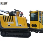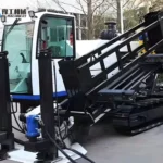
A crawler drill rig for pneumatic water-well drilling combines a mobile tracked base with a drilling system that rotates and advances a downhole tool. In consolidated rock, a down-the-hole hammer breaks material at the bit while compressed air helps carry the cuttings out. Tracks move the equipment; they do not determine how the bore remains stable or how the rock is broken.
The important product relationship is between percussion, rotation, feed and flushing. Increasing one setting cannot compensate indefinitely for a problem in another. The YG–200 configuration below illustrates the equipment involved, with particular attention to changing formations and the supporting air and drill-string systems.
Crawler Drill Rig Percussion, Rotation And Feed
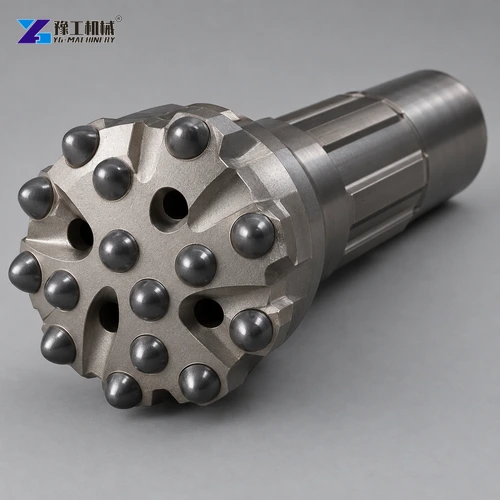
In a pneumatic DTH arrangement, compressed air passes through the drill string to the hammer near the bottom of the hole. Inside the hammer, the air-driven mechanism delivers repeated blows to the bit. The rig’s rotation unit turns the string so the cutting elements do not keep striking exactly the same points. Feed maintains the tool’s working contact with the formation.
These actions serve different purposes. Percussion fractures the material, rotation distributes the impacts, and feed controls contact. Excessive feed is not simply a faster version of correct feed: crowding the tool can interfere with stable drilling and cuttings removal. Inadequate contact can also produce ineffective operation. The appropriate relationship depends on the hammer, bit, ground and weight of the string, following their operating instructions.
The mast guides the drilling assembly and provides the working direction for feed. Its supported position matters to alignment and equipment loading. A crawler drill rig must be set up on suitable ground using the specified stabilizing arrangement before drilling; the ability to travel across a site does not establish that every stopping position is safe for operation.
As the hole deepens, the string becomes longer and its handling and loading change. A setting that worked near the surface should not be assumed suitable throughout the bore. Changes in penetration, rotation behaviour and returns provide information about what is happening below. A competent driller interprets those together rather than judging performance only by the time taken to add another rod.
This drilling family should not be confused with a core rig or a production blast-hole machine. A tracked machine may share a chassis arrangement with other equipment while using a different drilling method and tooling. The foundation and drilling equipment range provides that wider product context.
The hammer, rotation unit and feed system need to work as one drilling arrangement.
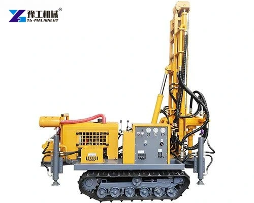
YG–200 Crawler Drill Rig Specifications
The following values identify the YG–200 crawler water-well configuration. They are equipment specifications, not a prediction of water yield, penetration rate or achievable depth in every geological setting.
| Parameter | YG–200 crawler water-well drilling rig |
| Drilling-hole diameter | 140–305 mm |
| Listed drilling depth | 200 m |
| One-time advance length | 3.4 m |
| Walking speed | 2.5 km/h |
| Using air pressure | 1.7–3.0 MPa |
| Air consumption | 17–30 m³/min |
| Drill-pipe length options | 1.5 m, 2.0 m, 3.0 m |
| Drill-pipe diameter options | 76 mm, 89 mm |
| Rig lifting force | 12 t |
| Swing speed | 45–70 rpm |
| Swing torque | 3,500–4,800 N·m |
| Dimensions | 4,000 × 1,750 × 2,450 mm |
| Weight | 5,800 kg |
The air-pressure and air-consumption rows describe different requirements. Pressure must suit the hammer and bore conditions, while the available flow participates in clearing the broken material. Neither row should be read as permission to connect any compressor within a broad catalogue category. The actual compressor, delivery line and hammer need a coordinated specification.
Likewise, advance length and rod length are not the same measurement. Feed travel concerns the movement available on the drilling assembly; rod length concerns the sections handled into and out of the string. Their relationship affects the working cycle, but does not establish a fixed drilling speed.
Lifting force is another limit that needs its correct context. The 12 t figure is not a promise that the rig can recover every stuck string, nor a general lifting approval for unrelated site loads. Equipment operating limits, tooling connections and the approved recovery procedure remain controlling. The selected rig should be understood through the complete configuration rather than choosing one large number as a substitute for compatibility.
Compare the YG–200 equipment figures with the tools and air system required for the bore.
Crawler Drill Rig Behaviour In Loose Cover And Rock
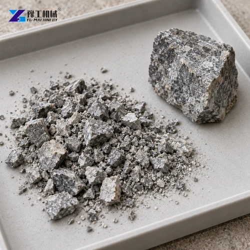
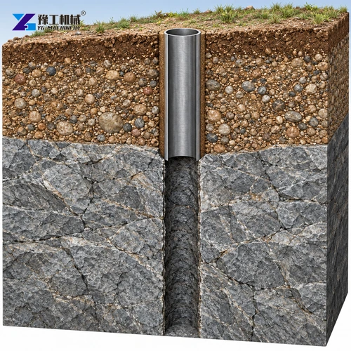
Competent rock and loose overburden present different drilling problems. In stable rock, the main task can be breaking and clearing the formation while maintaining a useful bore. In loose sand, gravel or highly weathered material, the wall may not remain open simply because the bit can penetrate it. Tool penetration and hole stability are separate questions.
Where an upper interval is unstable, the well design may require casing and a suitable method of advancing through that ground. The rig and handling system must support that chosen arrangement. An effective rock hammer at depth does not solve collapsing material near the surface. Nor should drilling fluid or casing be added as an improvised universal solution without considering the well-construction method.
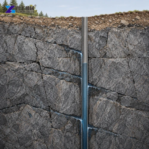
Fractured rock can behave differently from intact rock. Joints can release pieces larger than the ordinary cuttings, and broken zones may affect the return path or tool loading. A sudden change in drilling response can therefore indicate a formation transition rather than a reason to apply more force. The response has to follow the tool instructions and the contractor’s drilling plan.
Groundwater adds another variable. Water entering the bore changes what must be lifted to the surface, and the water level and inflow can influence the air-drilling task. The driller needs a method suited to those conditions, including controlled surface returns. There is no reliable universal rule that a larger compressor alone corrects every wet-hole problem.
For a water-well rig used across varying sites, formation information should guide the hammer, bit, support method and air arrangement together. The small electric water-well rig comparison describes a different equipment family; a shared water-well label does not make the two systems interchangeable.
Loose cover and competent rock require different parts of the drilling solution.
Air, Drill Rods And Cuttings Return On A Crawler Drill Rig
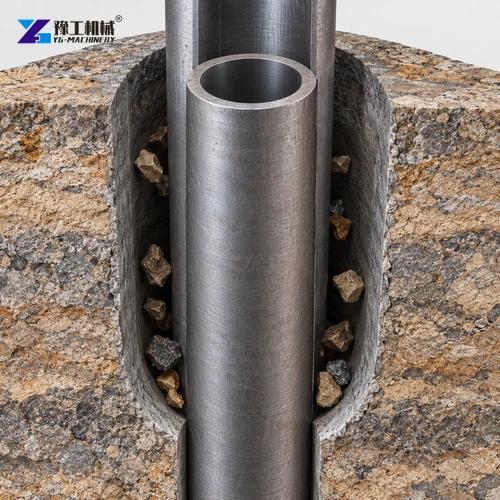
The material broken by the bit must leave the hole. In a conventional air-flushed arrangement, the returning stream carries cuttings through the annular space between the string and bore wall. If the hole diameter increases while rod size stays the same, that return area becomes larger. The air requirement is therefore connected to bore geometry, not only to the hammer’s ability to strike.
Poor clearing can leave the tool working in accumulated cuttings. The result can be inefficient regrinding, additional wear or unstable drilling behaviour. Forcing the rig forward does not remove the underlying transport problem. Returns should be assessed alongside feed, rotation and air supply, with changes made according to the equipment and drilling method.
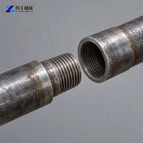
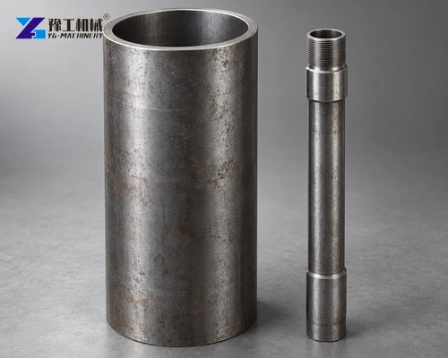
Drill rods transmit rotation and feed while providing the internal air path. Their diameter, length and connections must match the system. Worn or damaged connections can compromise reliable operation, and mixed incompatible strings should not be accepted because the nominal diameter looks similar. Inspection, handling and make-up practices need to follow the selected tooling instructions.
Compressor air must reach the tool through suitable hoses, fittings and connections. Restrictions, leakage and an inappropriate delivery arrangement can reduce the useful supply even when the compressor’s headline rating appears sufficient. The equipment package should identify that whole path. Compressed-air connections retain serious stored-energy hazards and require the prescribed restraints, isolation and pressure-release procedures.
Surface returns also need appropriate control. Dust, cuttings and any water should be managed under the site method rather than discharged wherever convenient. The rig supplies the drilling action, but does not by itself provide every part of a complete environmental or well-construction arrangement.
Match the compressor, rods and cuttings-return conditions together.
Crawler Drill Rig Tool Wear And Operating Precautions
Bit condition affects how impact energy reaches the rock. Worn cutting elements change the contact geometry and can reduce useful penetration even when the rig still supplies rotation and feed. A change in performance should prompt examination of tool condition and ground response, rather than repeated increases to the controls. Maintenance and replacement limits belong to the actual hammer and bit instructions.
Hammer lubrication and air quality need the same equipment-specific approach. The required lubricant, delivery arrangement and inspection routine should be established for the supplied tool. A generic oil quantity or maintenance interval borrowed from another model is not an appropriate substitute. Contamination entering the air or drill-string system can create additional wear and operating problems.
Rod handling is a repeated operation, not an occasional accessory task. The working area must keep people clear of moving assemblies and suspended or rotating components. A string that stops turning is not automatically safe to handle, and attempts to free a stuck tool can introduce loads different from ordinary drilling. Recovery requires the approved procedure and competent supervision.
The practical aim is stable drilling with a maintained tool, a supported machine and effective returns. A crawler drill rig is most useful when its controls are used to support that relationship, rather than treating maximum pressure, torque or feed as the default working condition. This approach also makes changes in the bore easier to recognize before a small problem develops into a damaged tool or interrupted well.
Crawler Drill Rig FAQs
No. Tracks provide mobility. In a pneumatic DTH setup, the downhole hammer delivers impacts while the drilling assembly provides rotation and feed.
Not by itself. Unstable cover may need casing and an appropriate drilling method. The support arrangement must be part of the well design and equipment package.
Pressure supports the hammer’s operation under the selected conditions, while flow also supports cuttings transport. Hole geometry, tool requirements and the air-delivery path must be considered together.
No. It describes the YG–200 configuration, not water availability or a guaranteed result in every formation. Well design and geology remain separate factors.
No. Bit wear, formation changes and inadequate cuttings return can also reduce performance. Diagnose the drilling system and follow its operating limits instead of simply adding force.
Tell us the intended well diameter and formation conditions to discuss a coordinated rig, tools and air package.