A hydraulic core drilling machine must advance the cutting bit while preserving the rock sample inside the core barrel. More feed force does not automatically produce a better sample. The useful arrangement balances rotation, axial feed, circulation and core recovery against the formation being drilled. For an exploration contractor, the purchasing question is whether those functions can be controlled together through changing ground.
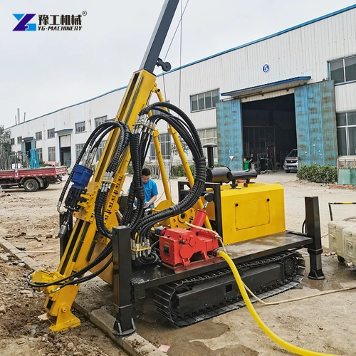
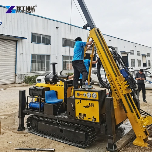
The YG-400, YG-600, YG-800 and YG-1000 are crawler-mounted hydraulic coring configurations with different depth, lifting-force and power entries. Their ratings help shortlist equipment, but sample quality also depends on the barrel, bit, drilling practice and geology. This article focuses on the connection between machine control and usable core, rather than treating maximum depth as the only selection criterion.
Hydraulic Core Drilling Machine Feed Must Match the Cutting Response
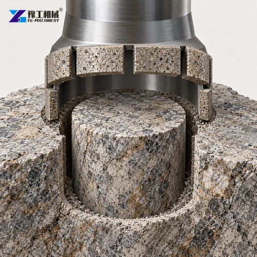
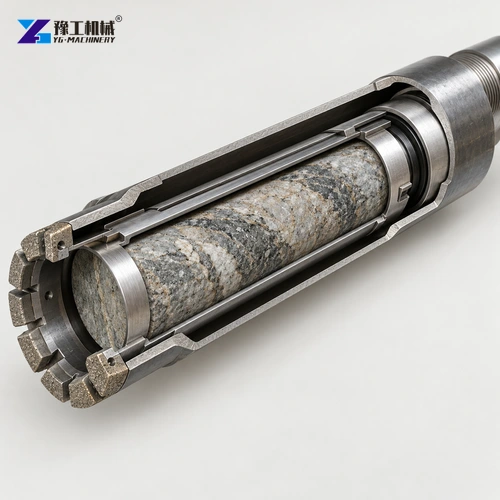
The bit cuts an annular path, leaving a cylindrical core rather than grinding away the entire bore. Rotation carries the cutting segments around that ring; hydraulic feed advances them into fresh rock. Feed that does not suit the cutting response can load the tool without producing proportionate useful penetration. Consequently, the relevant advantage of controllable feed is the ability to respond to changing ground, not a promise that the greatest force gives the fastest or best sample.
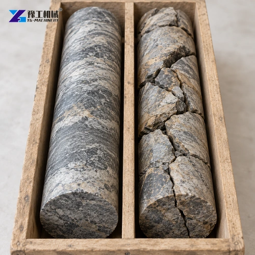
A hydraulic core drilling machine entering a fractured band faces a different problem from one cutting continuous competent rock. Pieces can move within the sampling path rather than remain as one supported cylinder. Advancing further is then not the same as preserving a representative record. The operator’s observations of cutting response, returns and recovered material belong together when judging whether the selected bit and barrel are serving the geological objective.
This distinction changes a purchasing demonstration. Watching a mast advance establishes movement, but not controlled sampling through a formation change. A useful comparison connects the feed and rotation controls to the proposed tooling and representative geology. Actual settings remain specific to the rig, bit and operating instructions; one pressure or speed should not be advertised as suitable for every rock type.
Discuss the rock condition and the sampling response the feed controls need to support.
Core Barrel Support Determines How Fragile Rock Reaches the Surface
The sample enters a barrel behind the cutting bit. Keeping the specimen supported is particularly important where joints or weak layers divide it into pieces. In compatible double-tube systems, the inner assembly separates sample containment from the outer rotating barrel; specialised additional liners or split-tube arrangements address particular recovery and handling needs. These are tooling choices, not features that should be assumed from the word hydraulic in the rig name.
For a hydraulic core drilling machine used on broken formations, ask what contains the sample during cutting and extraction, rather than asking only for more installed power. A barrel intended for intact rock may not answer a project that needs fragile intervals preserved for logging. Conversely, selecting specialised sampling tools without checking their rod connections and bore requirements can create a package the rig cannot use as proposed.
For example, two projects may specify the same final bore depth but need different samples. One may prioritise a continuous geological record through fractured intervals; another may require specimens for a defined testing programme. Compare the required specimen dimensions, barrel arrangement and handling method before comparing nominal rig capacity. Do not infer the recovered core diameter from the bore-diameter entry alone.
YG Hydraulic Core Drilling Machine Configurations
The table compares the published YG family as a complete configuration set. Depth entries identify nominal model capability, not a guarantee in every bore diameter or rock condition. Lifting force, power and transport dimensions change across the range; the sampling system and the proposed drilling programme still need to match the selected machine.
| Parameter | YG-400 | YG-600 | YG-800 | YG-1000 |
| Overall weight | 5.3 t | 6.7 t | 8.1 t | 9.2 t |
| Drilling diameter | 60–110 mm | 60–110 mm | 60–110 mm | 60–110 mm |
| Travel speed | 2.5 km/h | 2.5 km/h | 2.5 km/h | 2.5 km/h |
| Mud pump model | BW90-3 | BW90-3 | BW90-3 | BW160-10 |
| Drill pipe length | 1.5 m | 1.5 m | 1.5 m | 1.5 m |
| Lifting force | 10 t | 10 t | 12 t | 14 t |
| Dimensions | 4500 × 1950 × 2150 mm | 4600 × 2000 × 2350 mm | 5100 × 2200 × 2350 mm | 5150 × 2100 × 2150 mm |
| Drilling depth | 400 m | 600 m | 800 m | 1000 m |
| Maximum climbing entry | 30° | 30° | 30° | 30° |
| Drilling angle | 45–90° | 45–90° | 45–90° | 45–90° |
| Main machine power | 75 kW | 96 kW | 118 kW | 132 kW |
| Slewing speed | 0–1200 rpm | 0–1200 rpm | 0–1200 rpm | 0–1200 rpm |
The climbing entry is not permission to drill on an unsupported slope. Working position, support and transport requirements must be assessed separately. Likewise, the speed range does not prescribe one cutting speed for all bits. For the wider equipment relationship, see the YG foundation and drilling equipment collection.
Compare the YG configuration against the planned bore and matched sampling tools.
Core-Drilling Circulation Removes Cuttings Without Replacing Sample Support
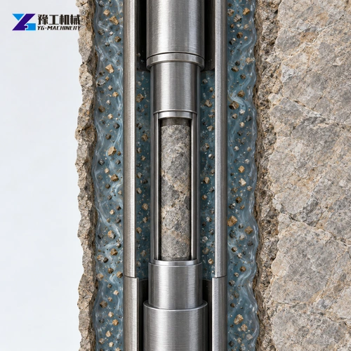
Fluid passes through the tooling’s designed passages to the cutting area and returns with cuttings through the bore annulus. This helps cool the bit and prevents the cutting face from repeatedly working against accumulated debris. The fluid path is therefore part of the cutting system, not merely a water connection to the machine. Its requirements depend on the bit, barrel and bore arrangement.
The YG range lists BW90-3 pumps on three configurations and BW160-10 on the YG-1000. Those names do not by themselves establish the correct flow or pressure for a chosen barrel. Confirm the complete pump specification and the tooling requirements for the programme. The hydraulic core drilling machine and its circulation package must be compatible with the actual operating method.
In weak or fractured ground, maintaining a fluid path and preserving a fragile sample can become competing concerns. Simply raising flow is not a universal answer: the chosen barrel must manage fluid around the sample in the way its design intends. Loss of returns also changes the evidence available to the driller. The proposed circulation and sampling package needs to address those ground conditions together, without promising a fixed recovery percentage.
Match circulation components to the selected barrel and ground conditions.
Wireline Retrieval Preserves the Sampling Cycle, Not Just Drilling Speed
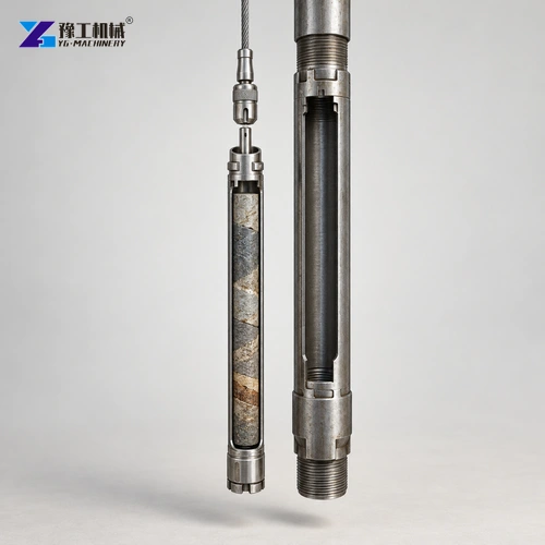
In a compatible wireline system, the inner assembly containing the sample is recovered through the drill string rather than requiring the entire string to be withdrawn for every core run. That distinction becomes more consequential as the hole deepens: rod handling and sample retrieval are different activities. The overshot, inner assembly and rods still need to belong to a matched system; the machine’s lifting-force rating alone does not prove compatibility.
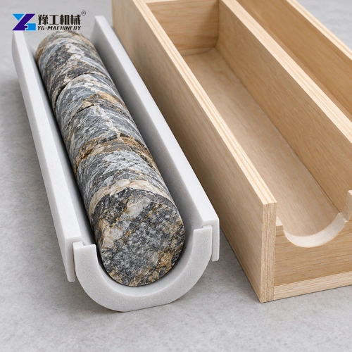
The recovered cylinder can contain both natural discontinuities and breaks introduced during drilling or handling. Keeping its sequence and depth context matters because a box of disconnected pieces is less informative if their order is lost. Careful transfer supports geological interpretation; it does not convert all recovered material into test-quality specimens. The testing programme determines which samples meet its requirements.
This is why hydraulic core drilling machine selection should include the recovery cycle as well as the drilling cycle. For related sampling principles, the mining core-drilling equipment guide explains the relationship between the rig, tooling and recovered material.
YG Core-Rig Selection Changes With Depth and Sample Fragility
For a shallower programme within the applicable configuration limits, increasing from a YG-400 to a YG-1000 does not by itself protect a fractured sample. The listed power rises from 75 to 132 kW and lifting force from 10 to 14 t, but the sample still enters a selected barrel through a selected bit. The higher-capacity machine addresses a different equipment envelope; it does not replace a formation-appropriate sampling system.
For a deeper programme, lifting requirements and the repeated recovery cycle become more significant, while the same distinction between metres drilled and useful sample remains. Compare a hydraulic core drilling machine as a package capable of reaching the target and preserving the evidence sought there. Depth, feed control, circulation and retrieval each answer a different part of that task.
Choose a rig and recovery package for the required geological sample.
Hydraulic Core Drilling Machine FAQs
No. Feed must suit the formation, bit and barrel. More force cannot compensate for unsuitable sampling tools and may disturb weak material.
No. Bore diameter and specimen diameter are different dimensions. Confirm the core barrel and bit combination against the required sample.
The YG-1000 configuration lists a BW160-10 mud pump. Confirm its complete specification against the selected tooling rather than assuming settings from the model name.
No. Rods, barrel, retrieval assembly and rig must form a compatible package. Tool connections and the manufacturer’s operating limits need to agree.
Compare specimen requirements, formation, tooling, lifting force, circulation, retrieval and site space. These factors explain whether a proposed configuration supports the sampling programme.
Tell us the formation, hole depth and diameter, required specimen and planned drilling location.