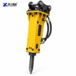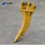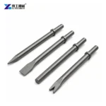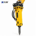


An excavator breaker converts carrier hydraulics into repeated impact at a replaceable tool. For road slabs, selection depends on pavement construction, carrier compatibility and a controlled removal sequence—not a generic attachment label.
Related product information: concrete breaker attachment and hydraulic breaker carrier compatibility.
What Does an Excavator Breaker Do in Road Slab Removal?
An excavator breaker converts hydraulic energy from the carrier into repeated impact at a replaceable working tool. On road slabs, the attachment is used to fracture concrete or other hard pavement so pieces can be separated and removed. It is not a saw, lifting clamp or complete road-reinstatement system.
The right purchase is defined by the actual pavement build-up, the excavator circuit and the planned panel sequence. Reinforcement, buried services, traffic access and fragment handling can be just as important as breaker size, so quote the attachment against a documented work area rather than a generic road-breaking label.
Selected YG Breaker Models for Carrier Review
| Model | Carrier Weight (t) | Chisel (mm) | Body Weight (kg) | Pressure (kg/cm²) | Oil Flow (L/min) |
|---|---|---|---|---|---|
| YG530 | 2.5–4.5 | 53 | 85 | 90–120 | 25–50 |
| YG600 | 2–5 | 60 | 140 | 90–120 | 25–50 |
| YG680 | 4–7 | 68 | 152 | 110–140 | 40–70 |
| YG750 | 6–9 | 75 | 210 | 120–150 | 50–90 |
| YG850 | 7–14 | 85 | 278 | 130–160 | 60–100 |
| YG1250 | 15–18 | 125 | 616 | 150–170 | 80–110 |
Use these model rows to shortlist a breaker, then match the excavator operating class, hydraulic pressure and oil flow to the same row. Slab thickness alone is not enough: pavement layers, reinforcement, tool choice and the removal sequence also matter. Compare the concrete breaker attachment range before confirming the carrier and working circuit.
Map the Road Slab and Removal Sequence
Record whether the surface is asphalt, plain concrete or reinforced concrete, and identify any overlay, base layer, joints and previous repairs. Thickness and reinforcement can change within one road section, so use drawings, cores or other approved site evidence instead of treating the pavement as uniform.
Mark the limits of each removal panel, the nearest live lane, traffic controls, access for the carrier and where broken material will be staged. The demolition attachment breaks material; saw cuts, lifting, loading and disposal remain separate work steps that must fit the same traffic window.
The field record should distinguish the existing surface from the final removal boundary. Photos with a scale, marked plan and notes on joints or patch repairs help a supplier understand where the breaker will start and what material the tool will meet.
Send a marked slab boundary, thickness and reinforcement details, nearby utilities and the excavator model; these determine the breaker size and a workable removal sequence for the road section.


Match the Breaker to the Excavator and Pavement
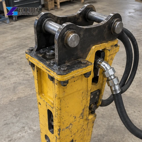
A hydraulic breaker assembly typically includes a carrier bracket, breaker body, working tool and hydraulic connections. Its impact class and tool shape must suit both the excavator and the material. Request the offered breaker model and compatible tool profile rather than choosing from excavator tonnage alone.
Match auxiliary flow, operating pressure, return-line limits, hose connections and coupler details for the exact excavator and breaker. A breaker that pins onto the arm can still be a poor match if its hydraulic range or installation geometry falls outside the carrier limits; that can reduce impact performance or place avoidable strain on the circuit.
Compare the breaker’s required flow, pressure and return limits with the excavator’s available auxiliary circuit. All values must suit the selected model pair; a fit in pin diameter alone does not prove that the breaker can operate correctly.

Choose a Controlled Break Pattern for Road Slabs
Start from a free edge or approved cut line and break in sections that can be handled by the available excavator and loading equipment. The sequence should avoid trapping an intact strip, pushing fragments into an open lane or undermining pavement that is meant to remain in service.
Use a trial area to confirm tool contact, fragment size, rebound and the time needed to separate the slab from its base. Work the tool as instructed by the attachment manufacturer; do not use the breaker as a pry bar or force the excavator to twist against a jammed chisel.
A short controlled trial helps reveal whether the slab separates cleanly or remains tied to reinforcement and the base. Use the result to refine panel size, loading order and the allowed work window.
To match a road-slab breaker, provide the excavator model and auxiliary-circuit range, slab layers and reinforcement, removal dimensions, nearby utilities, work window and destination. These details affect breaker size, tool choice and the safe removal sequence.


Protect Utilities, Reinforcement and Adjacent Pavement
Locate buried services and confirm the permitted excavation boundary before impact work begins. Where reinforcement, dowels or tie bars connect the slab to adjoining pavement, the project method must state whether they are cut, exposed or retained; the breaker alone does not decide that structural detail.
Plan dust, noise, flying fragments, vibration monitoring and exclusion zones according to the road owner and project controls. Protect adjoining asphalt and concrete from unintended cracking, keep workers outside the swing and fragment zone, and stop if the exposed construction differs from the approved removal plan.
Utility and road-owner requirements control clearance, monitoring and traffic arrangements. If field exposure reveals an unrecorded service or unexpected reinforcement, pause and obtain the project decision before continuing.
Prepare an Excavator Breaker Quote for Road Work
Send pavement drawings or measured layers, slab photos, reinforcement notes, removal area, carrier make and model, hydraulic data, coupler dimensions, daily work window and destination. Include the required breaker, bracket, tool, hoses, spare wear parts, packing and any requested commissioning or operator guidance as separate quote lines.
Ask suppliers to identify the assumptions behind tool selection and carrier fit. Keep road closures, saw cutting, lifting, traffic management, utility verification and debris haulage visible as project responsibilities unless a written offer expressly includes them. This makes competing equipment packages easier to compare.
A complete request also states the required quantity, destination, packing, delivery term and acceptance documents. Separate product supply from civil work and site approvals to avoid an ambiguous quote.
Send the excavator make and model, measured flow and pressure, pavement layers and reinforcement, removal dimensions, work window and destination. These details help match the breaker and tool to your road-slab job.
Inspect the Breaker and the Road Surface During the Shift
Before work, inspect the working tool, retaining components, pins, hoses, couplings and visible wear. Confirm the tool is seated and the breaker is mounted as instructed. At shift changes, record unusual movement, leakage, heat or loss of impact so a small fault is not hidden by changing ground conditions.
Track the actual pavement encountered, the area opened, fragment size and time spent on cutting, breaking, sorting and loading. These are job records, not a guaranteed production rate; they help the contractor plan the next closure and compare future equipment packages on the same basis.
After each panel, verify that the remaining edge is stable and the exposed base is ready for the next approved operation. Acceptance of the formation, disposal and reinstatement must follow the road project specification rather than the attachment quotation.
Excavator Breaker for Road Slab Removal: Plan the Work FAQ
Provide the pavement layers and thickness evidence, reinforcement details, removal dimensions, excavator model, hydraulic data, coupler measurements, access constraints and fragment-handling plan.
No. Material, reinforcement, slab construction, carrier compatibility and the permitted work sequence vary. Confirm the actual breaker and tool against the site conditions and project method.
Not automatically. Ask the supplier to list the breaker, bracket, tool, hoses, wear parts, packing and commissioning separately, and identify civil works, traffic control, lifting and haulage exclusions.