

A ripper tooth uses the excavator’s breakout force to loosen fractured weathered rock; a hydraulic breaker applies repeated impact where the tooth cannot enter. Match the observed rock structure, carrier and stop-or-switch rule before selecting one tool or a sequence.
Related product information: ripper tooth for excavator and concrete breaker attachment.
How Should a Ripper Tooth and Hydraulic Breaker Be Compared?
The choice turns on how the rock fails. A ripper tooth concentrates excavator breakout force to pull apart existing fractures; a hydraulic breaker delivers repeated impact where the tooth cannot penetrate. In weathered rock, the face may contain both conditions, so the useful question is where each method makes controlled progress without forcing the carrier.
On weathered rock, a ripper tooth can pull along fractures the excavator can engage; a hydraulic breaker applies repeated impact where the rock remains too intact for controlled ripping. Some faces contain both conditions, so a planned change of tool may work better than forcing one attachment across the whole area. The comparison below helps shortlist tools, but overlapping carrier classes do not mean equal performance.
Compare Ripper Tooth and Breaker Options for Weathered Rock
| Attachment | Model | Carrier Class (t) | Model Fit / Tool Details | Weight (kg) | Hydraulic Match |
|---|---|---|---|---|---|
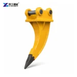
| Ripper tooth | YG-04 | 6–9 | 656 × 180 × 55 mm (L × W × thickness) | 85 | Confirm for carrier |
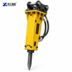
| Hydraulic breaker | YG750 | 6–9 | 75 mm chisel; 400–800 bpm | 210 | 120–150 kg/cm²; 50–90 L/min |
| Ripper tooth | YG-06 | 12–16 | 885 × 240 × 80 mm (L × W × thickness) | 185 | Confirm for carrier |
| Hydraulic breaker | YG850 | 7–14 | 85 mm chisel; 400–800 bpm | 278 | 130–160 kg/cm²; 60–100 L/min |
The overlapping carrier ranges are a starting point, not proof that these attachments will do the same job. A ripper tooth pulls material along fractures; a breaker uses impact through a chisel. Match the actual excavator mount and, for the breaker, its required pressure and flow; ask for the ripper-to-carrier fit for the exact excavator. Compare excavator ripper tooth options with the hydraulic breaker range.
Read the Fracture Pattern Before Selecting an Attachment
Start with exposed faces, natural joints, bedding, weathering depth and the size of blocks that the excavator can actually handle. Weathered rock is not a uniform material category: a decomposed surface over a competent core may call for a different sequence at each lift. Use site observations or the project’s geotechnical information instead of selecting by rock name alone.
Map access, working platform, dig direction, nearby structures and the staging area. The excavator must reach the face, remain stable and clear fragments without crossing the exclusion zone.
If the face has visible open joints and separable layers, a trial rip can show whether the tooth follows those weaknesses. If the tooth only scratches, skates or loads the boom without opening a crack, record that as a stop signal; repeated crowding does not prove the material is becoming workable.
Photograph the face from several distances and mark the observed joint direction, bedding and weathered-to-competent transition. A close-up without scale can hide block size; a wide photo without detail can hide the cracks that determine whether a tooth will enter.
Send a scaled photo of the weathered face and the excavator model; visible joints and the carrier’s reach help determine whether a ripper tooth can pull along fractures or a breaker is needed for repeated impact.
How Does a Ripper Tooth Engage Weathered Rock?
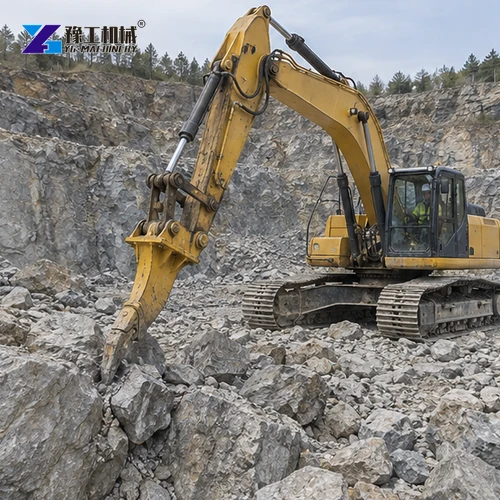
A conventional excavator ripper is a fixed shank and tooth that concentrates the carrier’s breakout force at a narrow point. It can loosen material that already has planes of weakness, allowing the operator to peel or separate pieces before digging and loading. It does not deliver the repeated hydraulic impacts of a breaker.
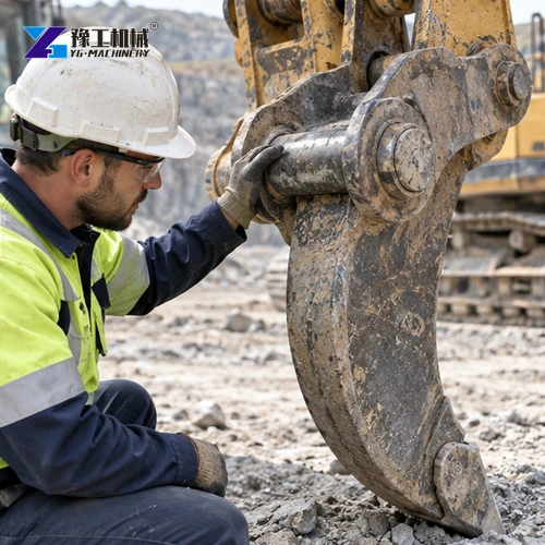
A ripper is relevant when fractures let the tooth penetrate and the excavator can pull through in controlled passes. Inspect the shank, tooth, bracket and pins; its mass and reach still affect boom and stability limits.
Ripping is not a substitute for a geotechnical assessment or an approved excavation method. Where a slope, unsupported face, buried service or adjacent structure could be affected, the site engineer’s controls determine the sequence and exclusion area.
Use a controlled test area to observe penetration and crack propagation; keep position and pass sequence consistent when comparing tools.


When Does a Hydraulic Breaker Become the Better Choice?
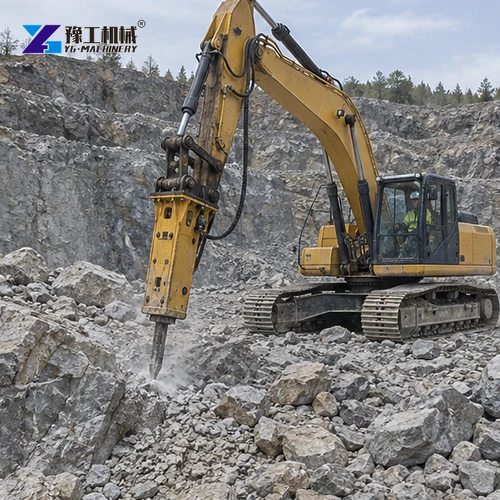
A hydraulic breaker applies repeated impact through a working tool. It can be the more appropriate attachment when a competent or massive section resists tooth entry and the excavator can supply the breaker’s documented hydraulic demand. The tool must be selected for the breaker model and material, not improvised from another series.
A practical switch decision is based on observed progress and carrier response: a tooth that repeatedly skates, no crack opening, rising structural strain or a machine beginning to lift off its tracks are reasons to stop and reassess. Do not use the ripper as a lever against a block that will not release.
A breaker also has limits. Confirm auxiliary flow, pressure, return conditions, hose routing, breaker mass, tool fit and carrier stability. Repeated impact can create noise, vibration, dust and fragments, so the work window and nearby asset controls need to be planned before the first strike.
Ripper teeth and breakers place different demands on the excavator. Match the ripper’s carrier class, mass and mounting dimensions to the machine; for a breaker, also check hydraulic pressure, flow and return requirements. At the planned reach and working angle, the excavator must remain stable with the selected attachment.
For a recommendation suited to your rock face, provide the excavator model and reach, photos of the exposed rock, working angle and site-access limits. Also note whether one attachment must handle the full cut or whether you can switch from ripping to breaking as the material changes.

Can One Excavator Use Both Attachments in Sequence?
On a mixed face, a project may rip the weathered layer and use a breaker only where the lower mass will not separate. Confirm this sequence with a controlled trial.
A quick coupler can reduce changeover effort only when the exact attachment interfaces, locking system and carrier limits are compatible. Verify the coupler and both attachment weights; never assume that a fast exchange is approved simply because pin centers appear similar.
Record the ground zone, attachment used, carrier position, pass sequence, visible crack response and reason for changing tools. That record helps the contractor refine the method without turning a single trial into an unsupported production promise.
Model specifications alone cannot predict how many metres of rock a crew will remove per hour. Rock structure, operator technique, access, fragment handling and work restrictions all affect cycle time, so use a representative site trial to plan production.
Prepare a Ripper Tooth or Hydraulic Breaker Quote
Send the excavator make and model, operating weight, coupler and pin dimensions, hydraulic specifications for the breaker circuit, reach, working angle and photographs of the rock face. Identify whether the request covers one attachment or a sequential package, and list the selected tooth or breaker tool separately.
A ripper tooth and a hydraulic breaker are not interchangeable just because both fit a similar excavator class. Compare mounting dimensions and attachment weight, then match the breaker’s hydraulic limits; choose the tool according to whether the weathered face can be pulled along fractures or needs repeated impact.
Keep the civil scope explicit: survey, scaling, temporary support, traffic control, dust suppression, fragment loading, haulage and disposal are not automatically included with an attachment. A written quotation should state the included bracket, hoses, pins, tools, wear parts, documents, packing and commissioning.
If quoting both tools, identify the compatible coupler, changeover equipment, storage, spares and operator switch rule.
Send photos of the exposed rock face, the excavator model, and its mounting and hydraulic details. The fracture pattern and carrier fit help determine whether a ripper tooth, breaker or staged combination suits your work area.
Set a Trial Rule for Stopping or Switching Tools
Before the trial, agree the authorized work zone, excavator position, permitted tool, communication method and observation points. Keep people clear of the boom, attachment and likely fragment path, and use the project’s controls for dust, noise and vibration.
For each trial pass, note whether the tooth enters the joint, whether the crack opens, how fragments release and whether the carrier remains stable. For breaker work, record tool contact, fracture response, repositioning and any abnormal hose, heat or machine behavior; these are observations, not guaranteed output figures.
Stop when conditions differ from the approved face, the attachment begins to skate or jam, the carrier loses stable contact, or an unrecorded service or structure is exposed. Reassess the method with the responsible site reviewer instead of applying more force.
After the trial, note which ground zones each attachment handled and why the operator switched tools. If the cut reaches a harder layer, these observations help plan the next work sequence instead of assuming the first layer represents the whole face.
Ripper Tooth vs Hydraulic Breaker for Weathered Rock FAQ
No. A ripper is suited to material that can be opened along existing weaknesses; a breaker may be needed where the rock is competent or the tooth cannot penetrate. Confirm the actual face and carrier setup.
The listed YG ripper model page gives carrier and physical-fit data rather than hydraulic flow or pressure. Verify the exact attachment and carrier documentation; do not assume hydraulic specifications from a breaker apply to a ripper.
No. Check attachment weight, mounting geometry, actual reach, stability, rock structure and, for a breaker, the carrier’s auxiliary hydraulic limits and return circuit.
Stop and reassess if the tooth repeatedly skates or fails to open a fracture, the carrier becomes unstable, or abnormal structural loading appears. Follow the approved site method before changing tools.