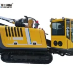
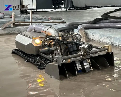
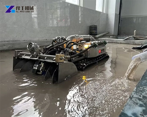
A dredging robot combines tracked movement, a front working assembly and a pumping system to collect settled material from a waterbody and move it through a discharge hose. An operator controls the system remotely while the working unit travels at the bottom. This makes the robot a complete sediment-handling arrangement, not simply a pump lowered into water.
The YG family includes different working widths, pump connections, motor sizes and particle-size specifications. Its practical value depends on matching the crawler to the floor and access conditions, then matching pumping and receiving arrangements to the material. A large pump figure alone cannot describe how quickly a particular basin will be cleaned.
Tracks, Working Head and Hydraulics Perform Different Jobs
The tracks position the working unit along the bottom, while the front assembly brings sediment toward the pickup area. The pump transfers the collected mixture of water and material into the discharge route. These jobs must remain coordinated. Moving faster does not improve cleaning if sediment is left behind; collecting material faster does not help when the downstream arrangement cannot receive it.
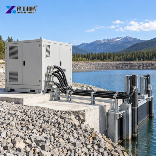
The shore-side hydraulic system, hoses and controls form part of the working setup. Remote commands let the operator control the equipment without standing at the submerged pickup point, but the robot still needs a managed connection to its supporting system. Hose movement, entry access and recovery remain practical operating tasks. Remote control should not be mistaken for autonomous route planning or a guarantee that no site supervision is needed.
Describe the sediment pickup task and shore-side equipment arrangement to discuss a connected system.
Dredging Robot Applications in Basins and Ponds
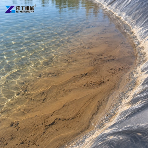
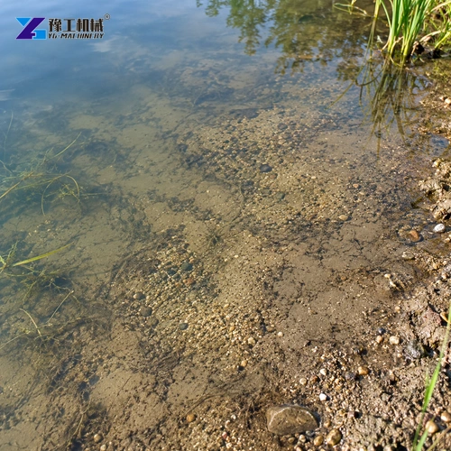
The equipment is relevant where settled material lies on a bottom the crawler can access and traverse. Industrial and municipal water-management teams, pond-maintenance contractors and facility operators may use a dredging robot for defined sediment-removal tasks. Their conditions differ, so the same machine width or pumping arrangement will not suit every waterbody.
Typical application discussions include:
- Settling basins: remove accumulated sediment from accessible floor areas while coordinating the work with inlet, outlet and receiving arrangements.
- Retention and drainage ponds: clear selected sediment deposits to support the site’s water-management plan, with attention to slopes and bank access.
- Industrial process-water basins: match the system to the material and operating environment, rather than assuming every sludge has the same handling requirements.
- Fishpond or reservoir maintenance: plan the work around the waterbody’s operating conditions, sediment characteristics and accessible bottom areas.
These are applications, not claims that one robot can handle every pollutant, depth or floor condition. Debris, liners, steep changes in level and unsuitable ground can change the working method. Define the cleaning task before choosing a machine. YG’s equipment support can discuss how the crawler and the rest of the system relate to that task.
Send the basin type, sediment and access conditions to review whether crawler-based cleaning fits the application.
YG Dredging Robot Models and Specifications
| Specifications | YG-500 | YG-600 | YG-700 | YG-800 | YG-900 | YG-1200 |
| Model | YG-500 | YG-600 | YG-700 | YG-800 | YG-900 | YG-1200 |
| Robot dimensions, mm | 1500×500×650 | 1500×600×650 | 1600×700×650 | 1600×850×700 | 1650×960×750 | 1900×1200×750 |
| Dredging width, mm | 500 | 600 | 700 | 800 | 900 | 1200 |
| Track travel speed, m/s | 3–15 | 3–15 | 3–15 | 3–15 | 3–15 | 3–15 |
| Robot weight, kg | 320 | 350 | 380 | 400 | 420 | 500 |
| Pump outlet diameter, inch | 3 | 3 | 4 | 4 | 4 | 4 |
| Pump flow rate, m³/h | 100 | 100 | 200 | 200 | 200 | 200 |
| Hydraulic station dimensions, mm | 2200×1200×1700 | 2200×1200×1700 | 2200×1200×1700 | 2200×1200×1700 | 2200×1200×1700 | 2120×1240×1200 |
| Main motor power, kW | 22 | 22 | 30 | 30 | 30 | 45 |
| Hydraulic system pressure, MPa | 0–16 | 0–16 | 0–16 | 0–16 | 0–16 | 0–16 |
| Particle size, mm | 15 | 15 | 38 | 38 | 38 | 60 |
| Reeling speed, r/min | 0–10 | 0–10 | 0–10 | 0–10 | 0–10 | 0–10 |
| Standard hydraulic hose length, m | 50 | 50 | 50 | 50 | 50 | 50 |
| Control system | Wireless remote | Wireless remote | Wireless remote | Wireless remote | Wireless remote | Wireless remote |
| Underwater LED lights | 2 | 2 | 2 | 2 | 2 | 2 |
Compare the model-specific dimensions and working width together. The station and robot are separate assemblies with separate space and handling needs. The travel-speed specification is not a sediment-removal rate, and the pump’s volumetric flow is not a dry-solids output rating.
Choose Working Width Around the Actual Bottom Task
A wider working head can cover a broader strip, but the useful choice depends on the accessible floor geometry. Narrow channels within a basin, structural columns, corners and restricted launch access may favor a more compact unit. An open floor can accommodate a different machine envelope. Compare the overall robot dimensions with access and maneuvering space, not just the head width.
Sediment characteristics influence pickup and handling. Fine silt, sand-bearing material and debris do not behave identically. The particle-size specification helps evaluate the relevant model, but it does not prove that long fibres, plastic, timber or every irregular object can pass through the equipment. Inspect representative material and consider how oversized or entangling debris will be managed.
A model comparison should connect three decisions:
- Working width to the strip of bottom that needs to be cleaned.
- Robot dimensions and weight to access, floor conditions and recovery arrangements.
- Material characteristics to the pickup system, particle specification and receiving method.
This links the machine to the work rather than selecting the largest dredging robot available. It also explains why a compact unit can be a better fit for a constrained basin even when a larger model has a broader working head.
Provide the bottom geometry and access constraints to compare working width and crawler dimensions.
Pumping and Receiving Capacity Must Work Together
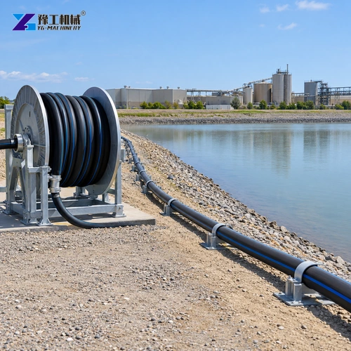
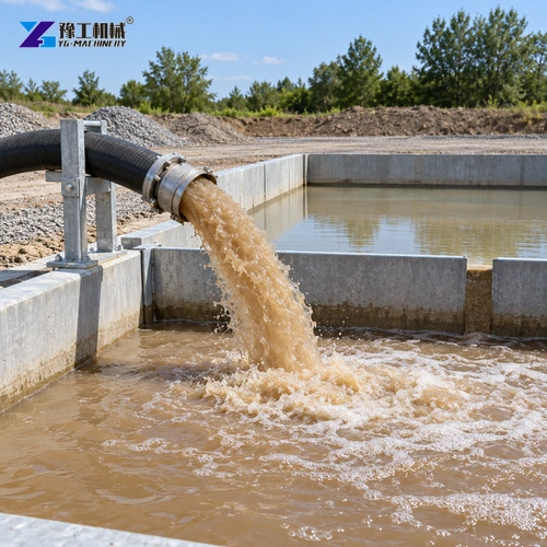
The pump moves a mixture through the hose. Sediment concentration, vertical lift, route length and bends affect the transfer task. A nominal flow value should therefore be considered within the actual discharge arrangement. Adding hose or changing the receiving elevation changes the system the pump has to serve; it is not simply extra storage added to an unchanged operating condition.
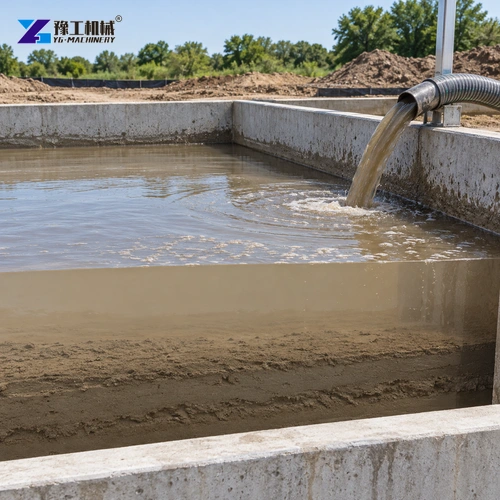
The receiving area must handle both the water and the removed material. A settling arrangement, a dewatering process or another approved handling method can control the pace of the operation. If material cannot be received or managed continuously, the crawler cannot use its potential effectively. Treat the dredging robot and the receiving process as one workflow rather than comparing only the submerged unit.
Discuss the route and receiving arrangement with YG’s dredging inquiry team when considering a complete system. This conversation should connect the proposed machine, hose management and material destination, without treating a pump rating as guaranteed job output.
Include the discharge-hose route and receiving arrangement when requesting a complete transfer-system proposal.
Dredging Robot FAQs
The YG system uses wireless remote control. An operator manages the work; remote operation is different from an autonomous robot planning and completing a cleaning route by itself.
No. Pump flow concerns the mixture transferred through the system. Sediment concentration, pickup conditions and the discharge arrangement affect the amount of solids removed.
Use working width for pass coverage and the overall dimensions for access and maneuvering. Robot weight and the supporting station also affect mobilization and site arrangements.
No. Fibrous, long or irregular debris can behave differently from a nominal particle. Evaluate the actual material and plan how unsuitable objects are handled.
It supplies and supports the working system from the site. Its position, access and hose connections need to be coordinated with launch, control and recovery of the crawler.
Select a Crawler and a Transfer System for the Same Job
A dredging robot is most useful when its working head, crawler envelope, pumping route and receiving arrangement support one defined cleaning task. YG Machinery can discuss those parts as a system. Start with the waterbody and material, then choose the model and supporting arrangement around the work that needs to be completed.
For a system proposal, include the waterbody, sediment, access, discharge route and intended receiving arrangement.