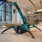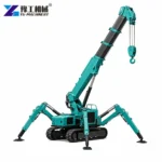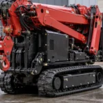
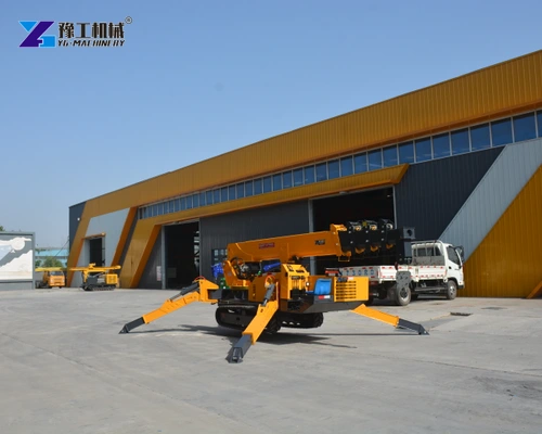
A mini crawler spider crane combines several movements in one compact lifting machine. Tracks reposition the chassis, outriggers support the working setup, the boom changes the hook’s reach, and the winch raises or lowers the suspended load. Understanding these separate jobs is useful when comparing equipment for installation and maintenance lifts.
The YG-5 example shows how boom geometry and rope movement contribute to hook placement during installation work. Comparing these functions helps distinguish the machine’s travel, support and lifting capabilities. A complete lifting plan uses the actual crane’s load chart and operating instructions for the intended configuration.
How Does a Mini Crawler Spider Crane Produce Its Working Movements?
The crane’s movements are related, but they are not interchangeable. Each changes a different part of the machine or load position. Separating them helps a buyer understand what the machine must do between picking up a component and setting it down.
- Crawler travel moves the chassis. Hydraulic motor drive turns the tracks so the machine can be repositioned in its permitted travel condition. Travel is a machine-mobilization function; a crawler chassis does not by itself establish a pick-and-carry rating with a suspended load.
- Outrigger deployment creates the working support arrangement. The legs extend the support footprint beyond the track base and transfer the working load into their ground contacts. Their permitted positions and contact conditions form part of the selected lifting configuration. Leveling and adequate support must both be established for that configuration.
- Boom elevation and extension change geometry. Raising the boom changes its angle; telescoping changes its length. Together they alter the position that the hook can reach. A longer extension does not preserve the crane’s maximum carrying figure at every position.
- Slewing changes direction around the crane. The upper working structure turns relative to the supported chassis. The suspended assembly and its path need to remain within the permitted setup throughout that movement.
- Winch movement changes the hanging rope length. Rope passes through the hook-block arrangement so the load can be raised or lowered relative to the boom tip. This is a different motion from extending the boom or raising the whole boom.
An installation lift may use several of these motions, but the operator selects the permitted combination for the actual configuration. The useful comparison is therefore the work envelope and controlled load movement, not the presence of tracks alone.
Describe the lifting movements the job requires so the crane functions can be compared with the task.
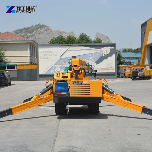
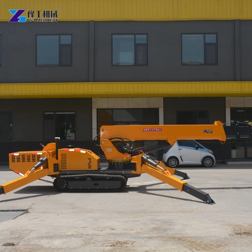
Mini Crawler Spider Crane Specifications
The YG-5 figures below describe one configuration in the family. They distinguish nominal capacity, a stated working-radius point, winch information and the machine’s physical size. Do not combine maximum values as though they occur in one lifting position.
| Parameter | YG-5 |
| Model | YG-5 |
| Nominal capacity designation | 5 t |
| Listed maximum working-radius point | 14 m with 0.5 t |
| Boom construction | Five-section, pentagonal structure |
| Listed boom length / extension time | 12.3 m / 54 s |
| Boom elevation range / time | 0–78 degrees / 13 s |
| Listed hook speed | 12 m/min, four-part rope arrangement |
| Listed wire rope | 11 mm diameter × 80 m |
| Slewing range / time | Continuous 0–360 degrees / 38 s |
| Travel drive | Hydraulic motor drive |
| Listed travel speed | 0–2.5 km/h |
| Transport dimensions | 5,000 × 1,500 × 1,900 mm |
| Total machine weight | 6,200 kg |
The 14 m entry is paired with 0.5 t. It is not a statement that 5 t can be lifted at 14 m. Equally, listed motion times do not predict the duration of a complete installation cycle: positioning, observing the load and making the final connection are additional parts of the work.
Transport size and self-weight serve a different planning purpose from lifting capacity. They describe the machine that must be transported and supported. For a closer explanation of the lifting relationship, see the working-radius and capacity guide.
Read capacity and radius as a matched configuration, then request the load chart for the proposed crane.
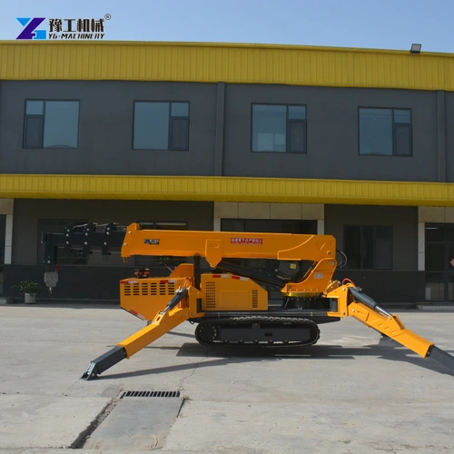
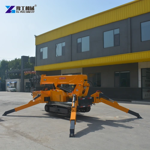
Winch, Rope and Hook Block on a Mini Crawler Spider Crane
The winch winds rope onto or off its drum. The rope is guided through the crane’s sheaves and hook-block arrangement, transferring the suspended load into the boom and supporting structure. The resulting load path explains why the rope arrangement belongs in the operating configuration rather than being treated as a loose accessory.
The YG-5 hook-speed entry is stated for a four-part rope arrangement. Reeving means the path the rope follows around the pulleys; four-part reeving has four rope sections supporting the moving hook block. The winch takes in rope along those supporting sections as the block rises, so rope speed and hook speed are different quantities. The listed 12 m/min hook speed belongs to that arrangement, not to every alternative reeving setup.
The hook block also forms part of the suspended assembly. Rigging and any lifting attachment add weight below the boom, so the machine must be assessed against the applicable load-chart rules for the complete assembly. An accessory that helps grip a component does not increase the crane’s lifting capacity.
Rope condition, correct reeving, hook-block condition and the applicable operating limits are checked through the machine’s instructions. The purpose is to preserve the intended load path. This is not a reason to improvise a different rope or hook arrangement to achieve an advertised speed.
Identify the complete suspended assembly and the specified rope arrangement for the proposed lift.
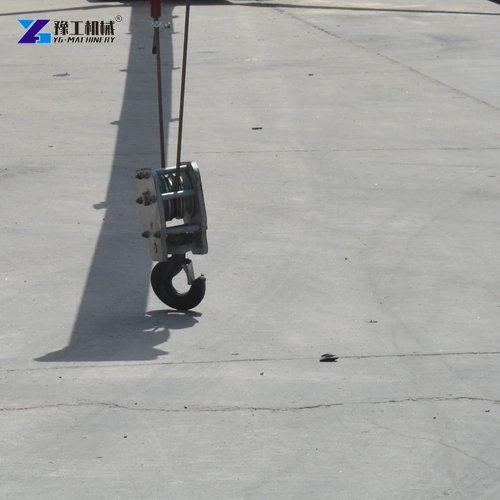
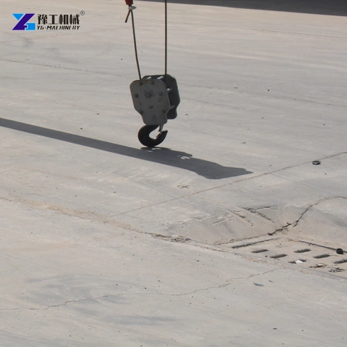
Boom Movement and Operator Control During Placement
Placement involves the component below the hook, not only the hook itself. After the crane has established the required reach and height, the component’s shape and rigging determine how its ends and faces approach the receiving location. A long beam can extend well beyond the hook position, while a compact motor presents a different placement outline.
For a vertical removal from a mounting position, the winch changes hanging height while the component must remain clear of its surroundings. For a beam approaching a receiving position, its orientation and projecting ends also require observation as the boom slews or changes reach. Swinging or rotation within the rigging can change those clearances without the boom tip moving in the same way. This is why the operator needs a view of the complete suspended assembly during placement.
The controls supplied with the crane define how its functions are commanded. The YG family offers manual operation and remote-control arrangements, but the chosen package needs to identify the actual control option. A radio handset changes where commands are issued; it is not an automatic placement system and does not eliminate the need for a suitable view and communication.
Ground support remains part of this moving geometry. A configuration that was appropriate at pickup must remain appropriate through the permitted movement and final placement. The ground-support and setup guide addresses that separate part of the lifting arrangement without replacing the crane’s instructions or lift-specific assessment.
Compare the required movement, observation and control arrangement before selecting the operating package.
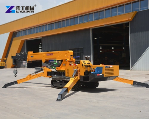
Mini Crawler Spider Crane Applications in Installation Work
The mechanisms above explain where this type of crane can be considered. Each application requires a suitable suspended assembly, receiving arrangement and permitted machine setup; the examples are equipment-selection situations, not claims about completed YG projects.
- Workshop machinery installation. A crane can lift a component from its permitted pickup condition and position it toward a mounting or receiving location. Boom geometry establishes reach, while winch control contributes to the change in hanging height. The final support and connection method belong in the installation plan.
- Steel-component placement. A beam or frame can have a large footprint relative to its weight. Its orientation and rigging affect clearance and the placement path. Nominal tonnage alone therefore cannot establish fit, even for a component lighter than the crane’s maximum designation.
- Maintenance component replacement. A motor or other removable assembly may need to leave a confined working position and reach a safe receiving support. Access to lifting points and the component’s complete travel path matter alongside the crane’s motions. The crane supplies lifting, not the machine’s isolation or dismantling procedure.
These tasks connect machine features with practical work: travel gets the crane to its location, the support arrangement establishes the working setup, and the boom and winch perform the permitted lifting movements. A useful spider-crane equipment enquiry describes the load and intended placement so the model, controls and lifting arrangement can be checked together.
Mini Crawler Spider Crane FAQs
No. Travel with a suspended load requires a specific permitted configuration and rating. Tracks alone do not establish pick-and-carry capability.
The listed 14 m working-radius point is paired with 0.5 t, not 5 t. Use the exact crane’s load chart for the actual boom, radius and support configuration.
Extension changes boom length and geometry. The winch changes hanging rope length through the hook-block arrangement. Both can affect placement, but they are different machine functions.
The YG-5 entry is stated as 12 m/min with four-part rope. A different reeving arrangement needs its own matching operating information; do not transfer the number without confirmation.
No. A remote provides the supplied operator commands. Observation, communication, the lifting plan and the equipment’s operating limits remain necessary for the complete suspended assembly.
Describe the load, rigging and intended pickup and receiving positions. YG can discuss a named crane configuration and the operating information needed to assess its assigned lifting task.