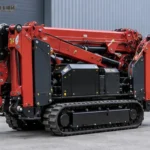
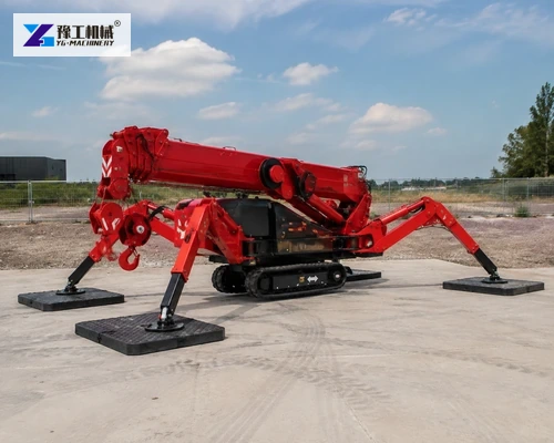
A mini spider crane is often selected because it can travel through restricted access and work close to a building. That compact footprint does not remove the need to verify the surface beneath the machine. During lifting, concentrated reactions pass through the deployed outriggers. A floor or paved area that carries the crawler tracks during travel may still be unsuitable for the lifting configuration.
This guide separates access, setup and lifting checks. Buyers can use it to gather the information a crane supplier and the responsible site engineer need before choosing a model, outrigger arrangement and support mats. It does not replace the model load chart or project-specific engineering approval.

Separate Travel Conditions From Lifting Support
Crawler contact distributes the machine’s travel weight over two tracks. Once outriggers are deployed, the load path changes. The reactions at individual feet depend on machine geometry, boom direction, working radius, lifted load and dynamic effects. Dividing machine mass by four is not a valid estimate of the maximum support reaction.
Record every surface the crane must cross and the final operating positions. A slab, suspended floor, buried-service corridor, compacted fill and landscaped ground require different evidence. Note edges, trenches, drains, basements and recent excavations because apparently level surfaces can conceal weak zones.
Published Mini Spider Crane Data For Initial Screening
The tracked mini crane page lists three reference configurations. These figures help screen transport and space requirements; they do not state allowable ground capacity or authorize a lift.
| Model | Rated capacity | Maximum working radius | Maximum hook height | Transport dimensions | Machine weight |
| YG3 | 3 t | 8.83 m at 0.15 t | 9.9 m at 0.7 t | 2950 × 980 × 1560 mm | 2700 kg |
| YG5 | 5 t | 14 m at 0.5 t | 16.8 m | 5000 × 1500 × 1900 mm | 6200 kg |
| YG8 | 8 t | 16.5 m | 18 m | 5000 × 1600 × 2180 mm | 7200 kg |
Capacity changes with working radius and boom arrangement. Use the exact configuration-specific load chart, including attachments and rigging. The published dimensions also show why gate width, turning room and setup space must be checked separately.
Send the load, required radius, access width and surface description so YG can identify which model data and support information are needed.
CHECK MY MINI SPIDER CRANE SETUP
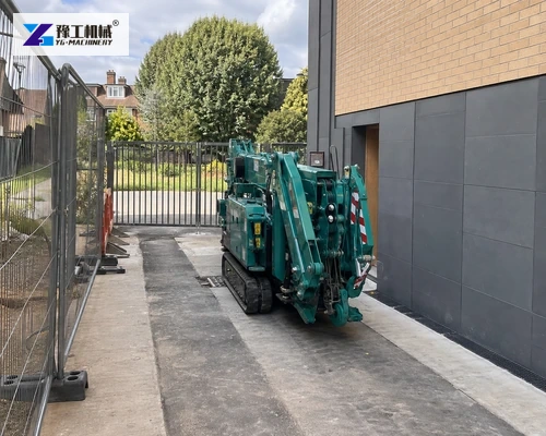
Build A Reliable Ground Information Package
Begin with site drawings and utility records, then confirm actual conditions. Photograph the full setup area rather than only the intended foot locations. Mark slab joints, edges, covers, drainage channels and changes in elevation. For soil or fill, provide the geotechnical information available and identify recent disturbance or water saturation.
Slabs And Suspended Floors
A concrete surface is not automatically a foundation. Confirm slab thickness, reinforcement, condition, support below it and the allowable concentrated load at the proposed positions. Suspended floors also require the structural system, spans and possible shoring to be reviewed by a competent engineer. Keep outrigger feet away from unverified edges and openings.
Soil, Fill And Temporary Working Platforms
Surface hardness alone is misleading. A thin compacted crust may cover soft or wet material. Provide soil classification, compaction records and allowable bearing information where available. The working platform should extend through the relevant load-spread zone, remain drained and be inspected after rain, excavation or repeated crane movements.

Size Support Mats From The Required Reaction
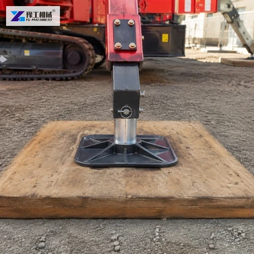
The basic comparison is maximum design reaction divided by usable bearing area. Both values need care. Obtain the support reaction for the actual crane configuration and lift direction, including the manufacturer’s required factors. Use the effective mat contact area that remains fully supported; do not count portions bridging a depression or extending over an edge.
Mat stiffness matters as well as area. A flexible pad may not spread load uniformly. Material, thickness, condition and orientation must suit the reaction and supporting surface. The responsible engineer should also consider punching, slab bending and underlying voids where a floor is involved.
Do not place loose packing under one side of a foot to correct a poor setup. Prepare a level bearing surface and use approved components. Every outrigger should remain within its permitted extension and the crane level tolerance specified by the manufacturer.
Provide the configuration-specific outrigger reaction and verified surface capacity. YG can help compare the required bearing area with the planned crane setup.
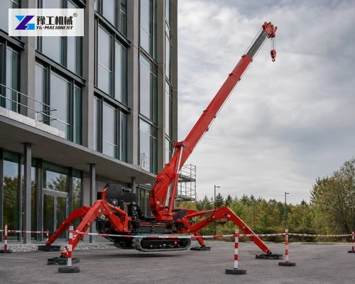
Access And Setup Geometry Control The Practical Model
Transport width is only the first access check. Measure gates, corridors, corners, ramps, overhead services and floor transitions. Confirm that the crane can reach the setup point with the boom stowed and that no turn requires the tracks to cross an unsupported edge. Protect finished floors using a method approved by the site owner without creating a slippery path.
At the operating point, draw the full outrigger envelope and the slewing area. Include barriers, pedestrian routes, doors and nearby operations. A model that fits through the entrance may not have enough clear space to deploy its outriggers in the load-chart configuration.

Verify The Lift At The Real Radius
Measure horizontal radius from the crane’s specified reference to the load’s center of gravity at pickup, during travel of the boom and at placement. Include rigging height and weight. The spider crane working-radius guide explains why a headline rated capacity cannot be applied at full radius.
Prepare a lift path, not just two points. The greatest radius or most restrictive boom angle may occur between pickup and placement. Identify how the load could rotate and whether wind or nearby structures change control requirements. Use the load chart for the exact outrigger and boom configuration.
Share the pickup and placement radii, hook height, load dimensions and rigging weight for a configuration review based on the complete lift path.

Inspection And Setup Records
Before lifting, inspect the access path, ground condition, mats, outriggers, safety devices and control system. Confirm the crane is level and each support is fully seated. Establish the exclusion zone and communication method, then conduct the checks required by the lift plan without suspending personnel near the machine.
Conditions can change during the job. Watch for settlement, mat movement, water, cracking or loss of level. Stop and reassess if any support changes. Record the selected model, configuration, chart reference, reactions, support details and site approval so the setup can be repeated or reviewed.
Keep the approved setup sketch with the lift documents and brief every operator and signaler. If the crane position, boom direction, load or surface changes, treat it as a revised setup and repeat the relevant checks before lifting resumes.
Send the complete lift and ground package when the site is ready for model and configuration confirmation.
DISCUSS MY MINI SPIDER CRANE PLAN
Mini Spider Crane Setup FAQ
No. Individual support reactions vary with boom direction, radius, load and crane geometry. Use the manufacturer’s configuration-specific reaction data and the project’s design method.
No. Thickness, reinforcement, support, condition, edges and concentrated-load capacity must be verified for the proposed foot positions.
Not automatically. The mat must be stiff enough, fully supported and compatible with the ground. A deeper weak layer or void may still govern the design.
Provide load and rigging weights, pickup and placement geometry, access measurements, surface information, setup photos, destination and any engineering limits already identified.