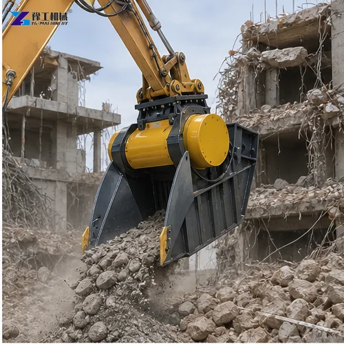
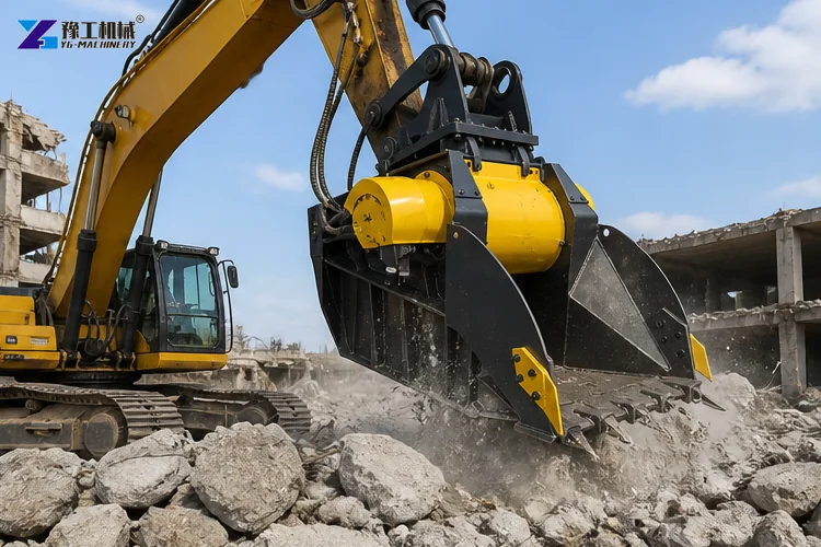
A concrete crusher bucket turns an excavator into a mobile jaw-crushing unit, but the number printed in a model table is not the volume a contractor can automatically sell or reuse each hour. Real output is the accepted fraction produced after loading, crushing, discharging, removing contamination and, where necessary, feeding oversize material again. The buying decision must therefore begin with the concrete stream and site workflow rather than a headline maximum.
This guide addresses production estimation. The existing excavator rock crusher bucket page remains the product and quotation reference. For tool sequencing before crushing, use the excavator demolition attachments workflow. Here, every capacity figure is treated as a comparison envelope that requires a representative trial.
Defining The Required Recycled Aggregate
Describe the feed by largest dimension, typical size distribution, concrete strength, reinforcement, asphalt, soil, wood and other contamination. State whether slabs arrive intact, after hammer breaking or after pulverizer separation. Long pieces bridge the inlet and heavily reinforced concrete consumes sorting time even when the jaw can break the surrounding material. Photographs need scale, and a sample pile should represent the difficult material rather than only clean blocks.
Define the required discharge fraction and its destination. Coarse engineered fill may accept a wider grading than a specified road-base layer. If the output must pass a screen, magnetic separation or laboratory test, count only material that meets that acceptance point. This prevents a supplier maximum based on one pass from being confused with usable tonnes or cubic metres.
Carrier Hydraulic Limits On Crusher Bucket Output
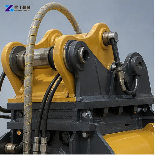
Match attachment mass and center of gravity to the excavator at the intended working radius. Then verify auxiliary oil flow, working pressure, allowable return or counter-pressure, hose diameter, coupler, electrical control and cooling capacity. A carrier that reaches the nominal pressure but cannot sustain the required flow will cycle slowly. Excess back pressure creates heat and can damage seals or the motor. Flow must be measured at the attachment circuit under realistic temperature where uncertainty remains.
The operator also needs enough stability and breakout control to pick, orient and feed material without dragging the bucket or overloading the linkage. Larger is not automatically faster: an oversized attachment may reduce mobility, visibility and usable working radius. The signed configuration should record hydraulic settings so another operator does not compensate for poor feeding by changing relief pressure.
Practical Crusher Bucket Production Calculation
Separate the cycle into approach and pickup, orientation, crushing, discharge, repositioning and unavoidable sorting. Observe several normal cycles, exclude neither minor jams nor routine rebar handling, and calculate productive cycles per hour. Multiply accepted volume per completed cycle by productive cycles, then apply shift utilization for refueling, inspection, jaw adjustment, stockpile moves and excavator relocation. Report a range for normal and difficult feed instead of one precise promise.
Bulk density changes after crushing, so do not mix bucket volume, loose output volume and tonnes without stating the measurement basis. Weighbridge data gives the strongest mass record. Where only volume is available, document how stockpiles or containers are measured and keep the conversion assumption visible. Compare the estimate with trucking and disposal avoided, not only with raw crushing speed.
Verified Model Values For Preliminary Comparison
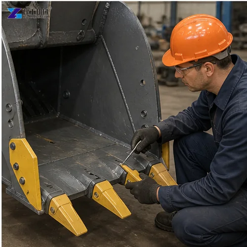
The current YG table lists eight hydraulic combinations. Oil flow ranges from 90 to 380 L/min and listed pressure from 200 to 250 bar. Published maximum production values range from 10 to 120 m³/h. These maxima help shortlist a model; they are not guarantees for reinforced demolition concrete, a specific gradation or a full shift.
| Model | Oil flow L/min | Pressure bar | Published maximum m³/h |
| YG-1 | 90 | 200 | 10 |
| YG-2 | 98 | 220 | 23 |
| YG-3 | 140 | 220 | 31 |
| YG-4 | 160 | 220 | 34 |
| YG-5 | 180 | 220 | 42 |
| YG-6 | 210 | 220 | 53 |
| YG-7 | 320 | 250 | 88 |
| YG-8 | 380 | 230 | 120 |
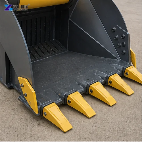
Output settings span approximately 15 to 200 mm depending on model. A smaller discharge gap normally increases reduction work and can lower one-pass production. The full model table must also be checked for carrier weight, attachment mass, opening and load capacity. One line cannot be selected from flow alone.
Discharge Size, Recirculation And Final Output
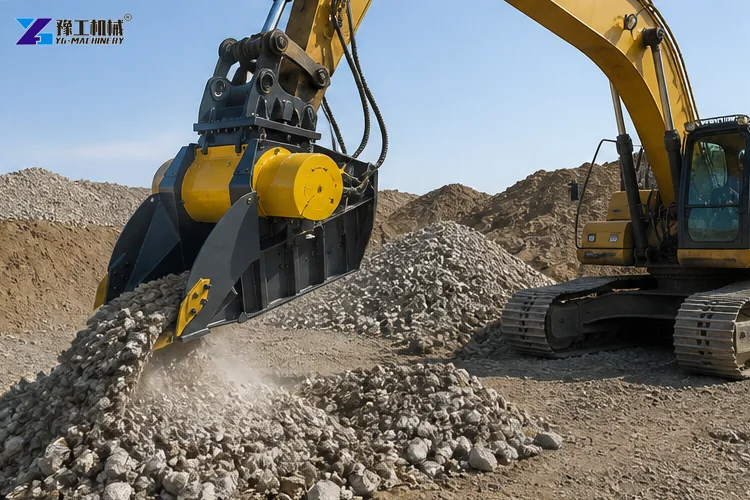
Record the jaw setting used for every trial. If the target is smaller than the one-pass product, estimate the share that returns for another pass and the excavator time required to collect it. A tighter setting may improve final size but increase wear, heat, fines and blockage risk. A wider setting may raise discharge rate while shifting work to a screen or secondary process.
Inspect jaw condition, cheek plates, bearings and the adjustment mechanism. Worn profiles can reduce bite and change grading before a dramatic failure appears. Track accepted output against hours and wear position. That record helps the buyer compare jaw life, adjustment time and production rather than treating wear parts as an unrelated maintenance expense.
Site Logistics That Reduce Productive Time
Lay out separate feed, oversize, steel, reject and accepted stockpiles. The excavator should feed and discharge without repeated long travel or mixing crushed product back into the demolition pile. Provide safe access for a loader, magnet or sorting crew and keep people out of the attachment working zone. Dust suppression, drainage and local environmental controls must be included before the trial.
Rebar should be exposed and handled according to the approved sequence; do not allow long steel to wrap around moving parts. Remove uncrushable items and define the response to a blockage. A reversible function can assist clearing, but it does not replace feed preparation. Shift output improves when the material presentation is consistent and another machine clears accepted product before the excavator loses its working position.
Factory And Site Acceptance Trial Records
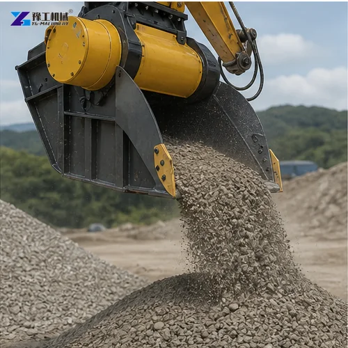
Use representative concrete at the proposed site or an agreed equivalent. Record carrier, coupler, oil temperature, measured flow and pressure, jaw setting, feed grading, reinforcement, test duration, cycle observations, fuel or operating hours, produced quantity and final grading. Photograph the starting pile and separated outputs. Repeat enough cycles to expose normal variation instead of timing one easy bucket.
Acceptance should cover safe mounting, hose routing, controls, reversal, guarding, noise and maintenance access as well as output. Retain the assumptions that could not be proven. If the trial uses clean unreinforced blocks, the agreement must not extend that result to mixed demolition rubble without another correction or test.
CONFIRM MY CRUSHER CONFIGURATION
Concrete Crusher Bucket Buyer FAQ
No. Feed, reinforcement, hydraulics, jaw setting, recirculation, operator cycles and site logistics determine accepted output.
The concrete can be broken and rebar exposed, but long steel and contamination require an approved preparation and separation method.
No. Attachment mass, carrier stability, hydraulic supply, opening, feed and working radius must all match.
Provide excavator model, auxiliary flow and pressure, coupler, feed photographs and dimensions, target fraction, required output, site layout and destination.
Please send your inquiry using the form below. YG will review the carrier, feed and accepted-output basis before confirming a model.