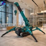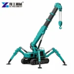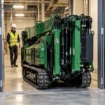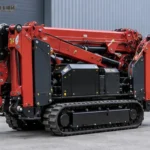
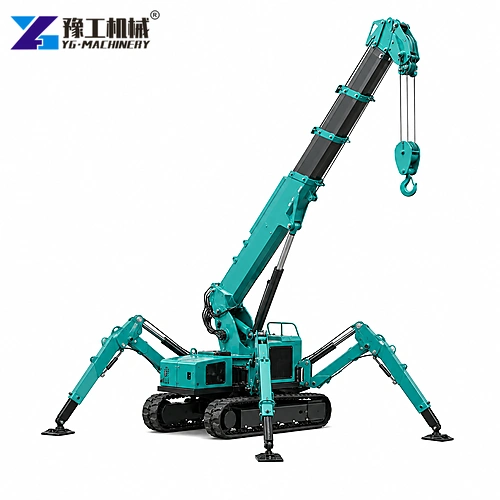
Spider crane lifting capacity is not the large number painted on a machine. Rated capacity falls as working radius and boom length increase, and the load chart may change with outrigger position or pick direction. Hook block, slings, vacuum lifter, spreader and below-hook accessories all consume capacity. A 3 t crane can therefore be the wrong choice for a much lighter panel if the panel must be placed far from the machine.
YG lists YG-3, YG-5 and YG-8 tracked mini cranes with maximum nominal capacities of 3, 5 and 8 t. The YG-3 is published at only 0.15 t at its 8.83 m maximum radius, while YG-5 lists 0.5 t at 14 m. Those examples show why a lift must be checked at the actual radius. The following workflow converts the load chart, site geometry and ground condition into a defensible model decision.
The examples use the published load and transport data for the YG tracked mini crane
, because rated capacity only becomes meaningful after working radius and outrigger geometry are known.What Weight Must Be Used For A Spider Crane Capacity Check?
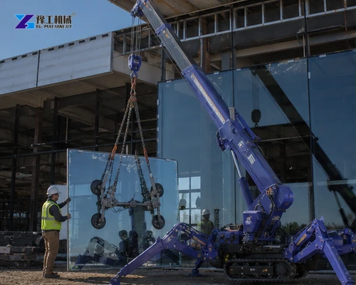
Use the verified gross load: component, packaging that remains during lifting, lifting beam, vacuum lifter, hook block, slings, shackles and any tag-line hardware.
Obtain an actual or certified weight whenever possible. A drawing estimate should include a documented allowance, particularly for fabricated pieces that may contain glass, sealant, fixtures or moisture not represented in a simple volume calculation.
Determine the load’s center of gravity and approved lifting points. An off-center lift can overload one sling leg and make the object rotate. Long panels may require a spreader to control sling angles, adding weight and headroom. The rigging plan should identify who connects, controls and releases the load and how people remain outside the suspended-load zone.
Share the lifted item, rigging weight, pick point and final placement. YG can help establish the gross load before a crane model is compared.
How Are Working Radius And Hook Height Measured?
The lift drawing must resolve horizontal reach and vertical clearance independently, then check both against the same permitted crane configuration. Neither maximum dimension can be combined automatically with the maximum capacity.
Working Radius Along The Whole Load Path
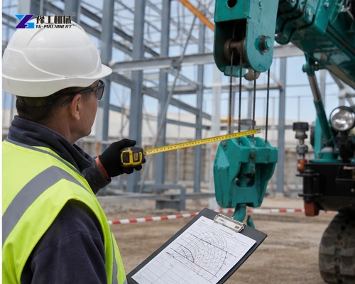
Working radius is the horizontal distance from the crane’s rotation center to the vertical load line, not the distance from the nearest outrigger. Measure the worst radius during pick, travel if allowed, and final placement.
Include walls, façade offsets, parapets and the need to keep the boom clear. A lift that begins close to the crane may pass through a larger radius before landing.
Measure radius from the crane rotation center to the load line at pick, travel where permitted and final placement. Draw the full path in plan and elevation. The worst point may occur while clearing a parapet or rotating around an obstruction, not at the start or end.
Hook Height And Rigging Headroom
Hook height must include the load, rigging, hook block and clearance above obstacles. Check whether the required boom length and angle appear in the same load-chart configuration used for capacity. A drawing should show plan and elevation. This prevents a selection that reaches high enough but cannot carry the load at the necessary horizontal distance.
Show the suspended assembly in elevation rather than marking only the final landing level. The load depth, lifting accessories and obstacle clearance consume the available height together. If the drawing changes the boom configuration, return to the corresponding chart; meeting a height dimension does not establish the capacity at that operating point.
How Does Published Capacity Change With Radius And Model?
YG-3, YG-5 and YG-8 list 3, 5 and 8 t maximum capacities, 9.9, 16.8 and 18 m maximum hook heights, and continuous 360° slew.
| Specification | YG-3 | YG-5 | YG-8 |
| Maximum lifting capacity | 3 t | 5 t | 8 t |
| Maximum working radius | 8.83 m at 0.15 t | 14 m at 0.5 t | 16.5 m |
| Maximum hook height | 9.9 m at 0.7 t | 16.8 m | 18 m |
| Boom | 5-section pentagonal | 5-section pentagonal | 5-section pentagonal |
| Slew | 360° continuous | 360° continuous | 360° continuous |
| Travel speed | 0–2.5 km/h | 0–2.5 km/h | 0–2.5 km/h |
| Gradeability | 36% (25°) | 36% (25°) | 36% (25°) |
| Transport dimensions | 2950×980×1560 mm | 5000×1500×1900 mm | 5000×1600×2180 mm |
| Machine weight | 2700 kg | 6200 kg | 7200 kg |
Maximum figures do not belong to one simultaneous operating point. The YG-3 maximum hook height is associated with a published 0.7 t value, and maximum radius is associated with 0.15 t. Always request the complete load chart for the proposed model, boom and outrigger configuration. Apply the supplier’s permitted deductions and site rules rather than creating capacity by interpolation.
Use the complete chart for the proposed boom and outrigger configuration. Maximum rated load, maximum radius and maximum hook height are normally different operating points. Apply all required deductions and working limits; do not interpolate capacity beyond values approved by the manufacturer.
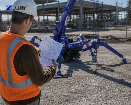
Send the required radius, hook height and site access drawing so the verified capacity data can be checked at the governing lift position.
How Do Outriggers And Ground Change Safe Capacity?
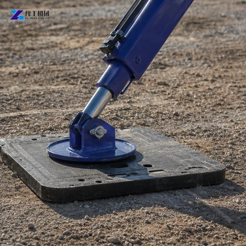
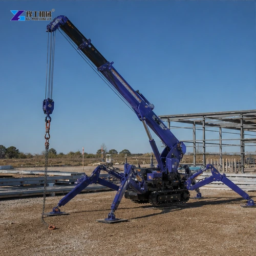
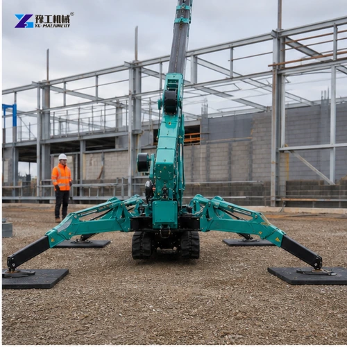
All four outriggers must be placed in an approved configuration on surfaces that can resist the calculated reactions. A compact crane can generate high local pressure despite its small footprint.
Obtain floor capacity for slabs and buried-service information for outdoor ground. Use engineered mats or spreaders sized for the reaction and surface, not a loose board selected by appearance.
Ground review should identify slab capacity, buried services, edges, voids and recent excavation. Calculate outrigger reactions and select suitable mats or spreaders. Recheck level and support after setup and after any weather or site condition that could change bearing performance.
Level the chassis within the manufacturer’s limit and keep each foot clear of edges, trenches and voids. Check that outriggers will not block emergency routes or collide with the load. Reassess conditions after rain, excavation or other site changes. Remote control improves visibility but does not change the load chart or eliminate the exclusion zone.
Can The Selected Spider Crane Reach And Occupy The Setup Area?
Transport width begins at 980 mm on YG-3, which supports restricted access. Machine weights are 2700, 6200 and 7200 kg; these values matter for transport, floor loading and setup.
Plan access from delivery through setup and removal, including doorway width, floor loading and overhead clearance. A crane that fits the lift chart may still be unable to reach the approved setup point.
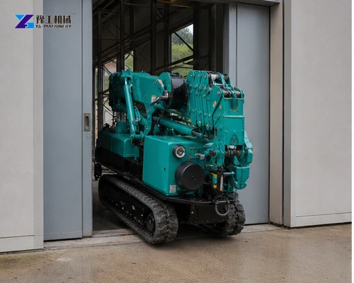
Check the route in the transport configuration separately from the working footprint. Doors and slab limits apply while reaching the setup point; outrigger space and maintenance or escape routes apply after deployment. Mark both arrangements on the site drawing so an access decision is not mistaken for permission to lift.
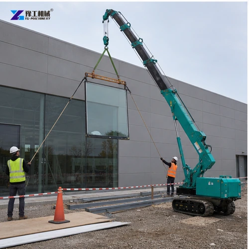
Schedule a pre-lift briefing using the approved drawing and load chart. Confirm roles, communication, exclusion, weather limits and stop conditions. A compact machine reduces access demands, but it does not reduce the discipline required around a suspended load.
Spider Crane Lifting Capacity Buyer FAQ
No. Maximum capacity normally applies close to the crane; capacity decreases with radius and boom length.
Yes. Hook block, slings, lifting beam and attachments are deducted from chart capacity.
Only after floor capacity, point reactions and suitable load-spreading protection are verified.
It can improve the operator’s view, but it does not change capacity or safe setup requirements.
Provide a plan and elevation showing crane center, outriggers, load path, radius, height and obstacles.
Submit a plan and elevation, verified gross load and the proposed setup surface below. The useful model comparison is the permitted operating point throughout the lift, not the largest capacity on the brochure. Final lift planning and ground approval remain with the responsible qualified parties.