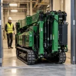
A small spider crane can position a glazing load from a restricted working area, but the glass, lifting attachment and crane have to be assessed as one lifting arrangement. The panel’s weight alone is not the suspended load. The lifting device and rigging add weight and occupy space, while the panel’s dimensions affect the route into its final position.
For glazing contractors, the useful buying question is whether the proposed machine can support the complete assembly through pickup, orientation and placement. Nominal crane class helps identify a starting model, but it does not approve a glass lifter or prove that a panel can be handled at the required reach. The YG crane configurations provide a basis for that equipment assessment.
A Small Spider Crane Positions the Hook; the Glass Lifter Controls the Pane
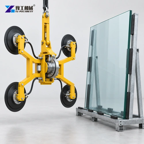
The crane and glass lifter perform different movements. Boom extension, luffing and slewing position the suspended assembly in space. A compatible glass lifter holds the pane and may provide a separate, specifically rated rotation or tilt function. A crane hook moving upward does not turn a horizontally stored pane into a controlled vertical installation. The required change in orientation determines what the lifting attachment must do.
A vacuum attachment depends on its approved suction surface and pad arrangement. A curved pane, a patterned surface and smooth flat glazing are not interchangeable loads merely because their weights match. The selected device’s material and orientation limits govern its use. A small spider crane quotation therefore needs a separately identified glass-handling package; the YG crane table does not establish that a vacuum device is included.
Consider the panel orientation at both ends of the lift. A unit collected from a stillage may need a different pose at the opening. If the lifting device can rotate or tilt, confirm the permitted movement and account for the changed position of the load. If it cannot, another approved handling arrangement is necessary; the crane’s boom movement does not automatically provide controlled panel rotation.
Include a glass-handling device suited to the pane and its required orientation.

Glass-Lifter Mass and Working Radius Change Available Crane Capacity
The crane carries the pane and the attachment, not just the customer’s glass weight. A hypothetical 200 kg pane with a 60 kg lifter already creates 260 kg before other applicable lifting items and chart deductions. These figures illustrate the arithmetic only; they are not a YG lifting approval. The selected machine’s chart must be checked at the actual working position under its specified setup.
Working radius is the horizontal relationship to the load, not simply the boom’s visible length. Reaching over a projection can place the suspended load farther from the crane’s centre than a direct lift beside the machine. The YG-3’s published 8.83 m at 0.15 t entry illustrates why nominal class and end-reach payload must not be confused: three tonnes is not available at that listed outer working point.
For a small spider crane, this combined assessment prevents a common selection mistake: choosing the nominal tonnage first and adding the real lifting attachment later. The later addition can change available capacity and clearance. Establish the assembly early enough that the machine and lifting package can be compared on the same basis.
Panel Rotation Needs Clearance Beyond the Finished Window Opening
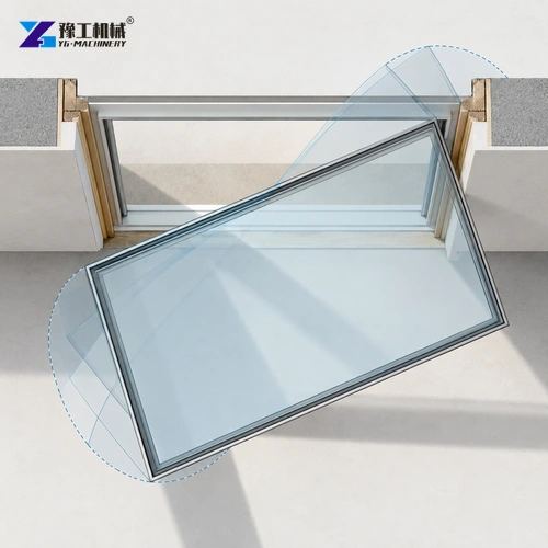
A rectangular pane turning toward an opening sweeps its corners through space outside its final outline. The pane may fit the completed frame while its approach conflicts with a canopy, scaffold or adjacent return wall. The lifting frame also stands proud of the glass and occupies part of the gap between the pane and surrounding structure. A slim attachment can solve a different problem from a higher-capacity crane.
This is particularly relevant to corner glazing. The pane must arrive in the required plane, with the attachment able to remain supported and later be released through the available space. A small spider crane may have sufficient charted capacity yet fail this geometric test. Increasing nominal tonnage does not make a bulky lifting frame thinner or provide a missing tilt function.
For example, moving a tall unit through a side approach can create a different clearance problem from raising it directly in front of the opening. The same pane and crane class may therefore need different setups. Evaluate the actual approach and landing point before deciding that a larger nominal model is the answer.
Check the attachment depth and approach to the actual window opening.

YG Small Spider Crane Model Comparison
These figures compare the YG-3, YG-5 and YG-8 crane configurations. A paired radius-and-load entry is one published working point, not a replacement for the complete load chart. The YG-8 maximum-radius entry does not state an associated load.
| Parameter | YG-3 | YG-5 | YG-8 |
| Nominal class | 3 t | 5 t | 8 t |
| Maximum working radius entry | 8.83 m at 0.15 t | 14 m at 0.5 t | 16.5 m; load not paired |
| Maximum above-ground height entry | 9.9 m at 0.7 t | 16.8 m | 18 m |
| Hook speed, four-rope arrangement | 0–8 m/min | 12 m/min | 12 m/min |
| Rope diameter and length | 8 mm × 45 m | 11 mm × 80 m | 11 mm × 80 m |
| Boom construction | Five-section, pentagonal | Five-section, pentagonal | Five-section, pentagonal |
| Boom length/time entry | 3.1–9.2 m / 20 s | 12.3 m / 54 s | 12.3 m / 54 s |
| Boom angle/time | 0–78° / 13 s | 0–78° / 13 s | 0–78° / 13 s |
| Continuous slew/time entry | 360° / 60 s | 360° / 38 s | 360° / 38 s |
| Travel drive | Hydraulic motor | Hydraulic motor | Hydraulic motor |
| Travel speed | 0–2.5 km/h | 0–2.5 km/h | 0–2.5 km/h |
| Travel/boom/outrigger operation | Manual; remote option | Manual; remote option | Manual; remote option |
| Transport dimensions | 2950 × 980 × 1560 mm | 5000 × 1500 × 1900 mm | 5000 × 1600 × 2180 mm |
| Machine weight | 2700 kg | 6200 kg | 7200 kg |
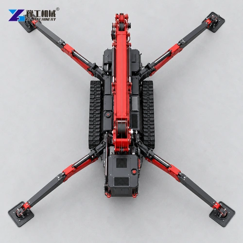
The table helps shortlist a class and physical envelope. It does not authorise the heaviest load at every height or radius. Review the YG tracked mini crane range for the core product relationship, then request the exact chart and lifting-attachment scope for the proposed setup.
Compare the complete suspended load with the applicable YG chart.

Spider-Crane Outriggers and Glass Surface Area Create Different Limits
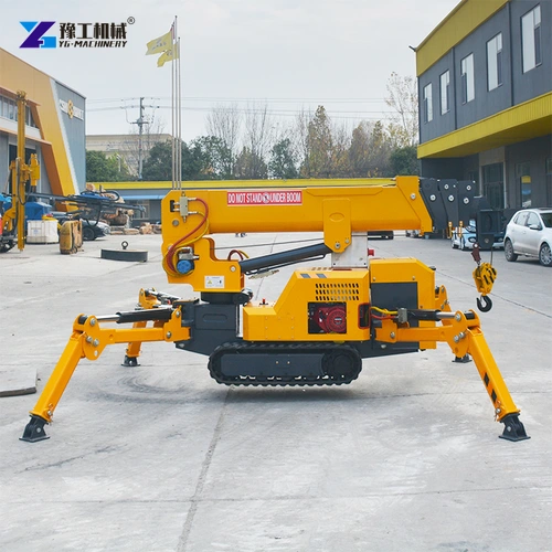
Crawler travel width is useful at the access stage; deployed outriggers establish a different working footprint. A machine that enters a doorway is not thereby approved to lift on the floor beyond it. The supporting surface receives concentrated reactions through the outrigger feet, so the floor or ground assessment must use the selected crane’s actual supported configuration rather than divide total machine weight equally by four.
Keep the panel route, lifting-device checks and crane setup visible in the same plan. That allows the lifting team to identify whether a change in machine position affects reach, clearance or supporting ground. For related access considerations, see the restricted-access mini crane guide.
The glass introduces another limit: its broad face can interact with wind even when the pane is relatively light. Crane capacity does not override the permitted conditions for a large surface-area load or the glass lifter’s own restrictions. Support, charted capacity and attachment suitability are three separate checks, each necessary for a coherent glazing package.
Choose a Glazing Package for the Limiting Part of the Lift
If the limitation is capacity at the required radius, a different crane class or approved position may be relevant. If it is the space between scaffold and façade, the lifting frame’s depth and movement may be the decisive factors. If the pane cannot be held by the selected suction system, more crane capacity answers the wrong question. These alternatives explain why a glazing proposal needs more than a nominal-tonnage comparison.
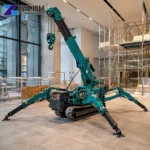
A small spider crane becomes useful when its compact access, supported working position and charted reach work with the chosen glass device through the entire intended movement. The quotation should identify which crane, lifting device and accessories provide that arrangement, with the applicable charts and instructions. It should not hide an unselected attachment behind a generic glass-installation photograph.
Identify the crane, lifting attachment and accessories in one clear proposal.

Small Spider Crane FAQs
Only when the quotation explicitly includes a compatible, approved device. Establish its specification and operating limits separately from the crane class.
Yes. Establish the complete suspended assembly and follow the crane manufacturer’s chart deductions and hook-block rules.
The listed maximum radius is 16.5 m without a paired load. Obtain the applicable load chart rather than inferring capacity from the eight-ton class.
No. Panel orientation depends on the approved lifting attachment and handling method. Boom movement alone does not establish that capability.
Its dimensions, surface area, attachment geometry and final pose can govern clearance and permitted handling conditions even when its weight is relatively low.
Include panel dimensions, weight, lifting-device details and the pickup and installation positions.