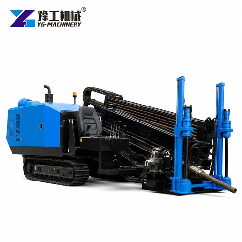
The horizontal directional drilling process installs a pipe or conduit along a guided underground path with limited surface excavation. A successful crossing depends on survey, utility locating, bore geometry, soil, steering response, drilling fluid, reaming and product-pipe strength. The rig is only one part of the system. A machine with enough pullback force can still fail when the bore path is too tight, fluid returns are lost or the reamer is selected without geotechnical evidence.
YG HDD models range from 160/100 to 320/320 kN maximum pull/feed force and from 5000 to 12000 N·m powerhead torque. Published maximum reaming diameters extend from 600 to 800 mm. These values support preliminary comparison, while the final model and tooling must be checked against bore length, ground, pipe diameter and drag. This article follows the construction sequence and identifies the evidence needed before quotation.
The construction sequence below is tied to the pullback, torque, rod and mud limits of YG horizontal directional drilling equipment
, so the rig is evaluated as one part of the bore system.What Must Be Surveyed Before The Pilot Bore Starts?
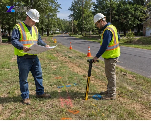
Confirm the entry and exit areas, existing utilities, surface levels, water bodies, roads, structures, access and permitted work limits. Use the required locating methods and verify critical crossings with exposure or another approved procedure.
The utility survey should combine records, field locating and approved exposure at critical conflicts. Show horizontal and vertical tolerances on the bore profile. If an unknown service or obstruction appears, the stop and redesign route must already be agreed so production pressure does not replace the safety decision.
A plan and profile should show depth, cover, bend radius and separation. Unknown utility positions are a stop condition, not a steering problem to be solved during drilling.
Investigate soil and groundwater along the full path. Fill alone does not describe cobbles, boulders, abrasive sand, sticky clay or flowing water that may appear at depth. The investigation guides bit, reamer, drilling-fluid program and contingency planning. Identify where fluid returns are expected and how inadvertent returns will be contained, reported and corrected.
How Is The HDD Pilot Bore Steered And Verified?
Set the rig to the designed entry angle and confirm anchoring before rotation and thrust begin. The drill head follows a planned series of controlled corrections.
Steering over a very short distance can create a tight radius that the rods or product pipe cannot follow. Record depth, pitch, heading and rod count continuously so the as-drilled path can be compared with the design.
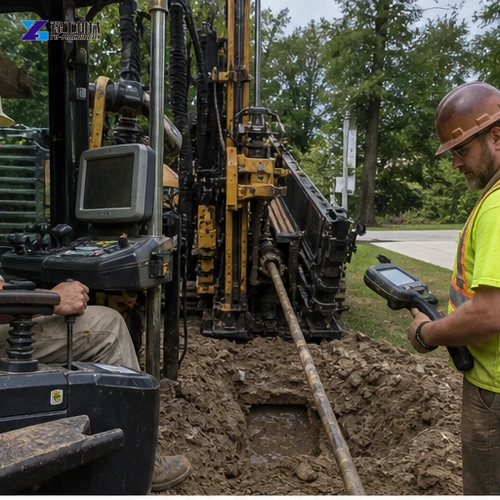
Locator records should capture rod count, depth, pitch and heading at the specified interval. Compare these points with minimum cover and product-pipe bend radius before enlarging the hole. A smooth plotted path is more useful than isolated readings because it reveals accumulated steering corrections.
The locator and rig operator need a clear communication method and agreed stop commands. Readings should be checked around interference, roads and critical utilities. If the pilot deviates beyond tolerance, evaluate the safest correction or redrill instead of forcing the string. The completed pilot path must be accepted before the team commits to larger tooling.
Where Do Rig Force, Torque And Mud Limits Enter The Bore Plan?
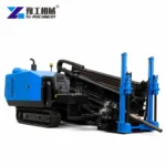
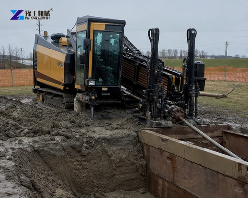
The YG-160A through YG-320A range increases pull/feed force, torque, rod diameter and mud-flow capability.
| Model | YG-160A | YG-180 | YG-280 | YG-320 | YG-320A |
| Engine power | 100 kW | 97 kW | 160 kW | 140/160 kW | 160 kW |
| Maximum pull/feed force | 160/100 kN | 180/180 kN | 280/280 kN | 320/320 kN | 320/320 kN |
| Powerhead torque | 5000 N·m | 6000 N·m | 10000 N·m | 12000 N·m | 12000 N·m |
| Maximum reaming diameter | 600 mm | 600 mm | 750 mm | 800 mm | 800 mm |
| Drill rod | 3 m × 60 mm | 3 m × 60 mm | 3 m × 73 mm | 3 m × 73 mm | 3 m × 73 mm |
| Maximum mud flow | 160 L/min | 250 L/min | 320 L/min | 320 L/min | 320 L/min |
| Maximum mud pressure | 100 bar | 80 bar | 80 bar | 80 bar | 80 bar |
| Machine weight | 6700 kg | 8500 kg | 12500 kg | 11500 kg | 11200 kg |
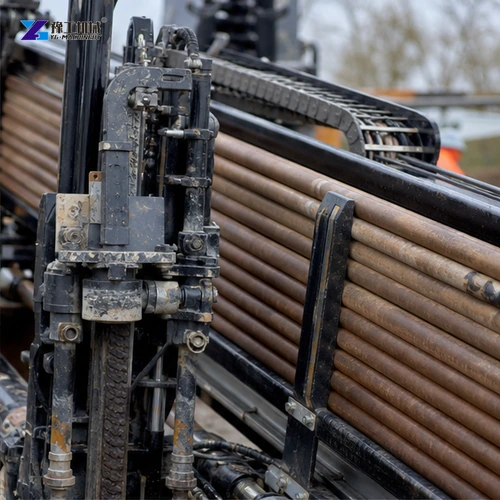
YG-160A uses 60 mm rods and up to 160 L/min mud flow, while YG-280 and both 320-class models use 73 mm rods and up to 320 L/min. Greater values support larger tooling and difficult ground but also increase machine size, transport and setup requirements.
Maximum reaming diameter is a catalog boundary, not a guaranteed diameter at every bore length and geology. Calculate estimated drilling-string drag, reamer load, pipe drag and a justified contingency, then compare them with allowable rig capacity and product-pipe pull limit. Mud pump pressure, mixing capacity and fluid volume must also keep the hole supported and cuttings moving.
Send the bore profile, ground information, product pipe and crossing length. YG can check whether the proposed force, torque and staged reaming plan fit the available rig range.
How Does Fluid Support Fit The Horizontal Directional Drilling Process?
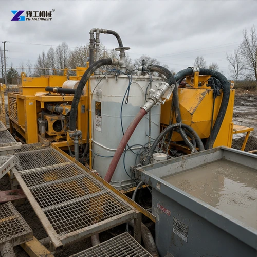
Production planning should also cover water supply, fluid mixing, solids control, spoil handling, restoration and environmental limits. These supporting systems can stop a correctly sized rig, so their capacities and responsibilities belong in the same crossing plan.
The fluid program must be considered alongside the rate at which cuttings are generated and removed. Catalogue pump limits describe equipment boundaries, not a ready-made recipe for every soil. Record the proposed ground conditions, expected returns and supporting mixing or solids-control equipment together before assuming that the rig pump alone defines the system.
How Should Reaming And Pullback Be Sequenced?
Hole enlargement and pipe installation are separate decisions. Accept the condition of the enlarged bore before committing the product pipe, and retain a record of the limits governing each stage.
Staged Reaming And Bore Conditioning
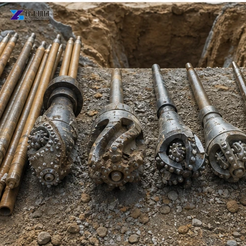
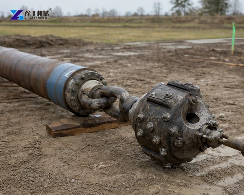
Select reamer type from soil and increase diameter in controlled stages when one pass would overload the formation, rig or fluid system. Monitor torque, pull force, rotation, fluid pressure and returns.
Estimate pilot, reaming and pullback loads separately. Ground and drilling-fluid returns can change between stages, so maximum rig pull does not prove that one large reamer is appropriate. Define monitoring limits for torque, thrust, flow and returns and state the response when a limit trends upward.
Slow penetration, rising torque or lost returns require investigation. Swabbing and conditioning passes may be needed to remove cuttings and stabilize the hole before product installation.
Product-Pipe Preparation And Controlled Pullback
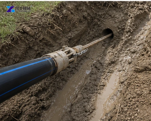
Inspect and fuse or join the product pipe in a clean line that respects minimum bend radius. Use a suitable swivel between reamer and pipe, verify the pull head and protect the pipe from sharp ground at the exit. Record pullback force and stop before exceeding the pipe or rig limit. A rushed pullback can damage an otherwise successful bore permanently.
Before pullback, inspect the joined product pipe, pull head, swivel, roller supports and exit geometry. Record actual pulling force and protect the pipe from sharp contact. Handover should include the as-drilled profile and material records, not only the rig model and completed length.
Keep the product-pipe records associated with the accepted bore profile. A pipe that can tolerate the planned curve may still need a different installation arrangement if the exit support or joining area changes. Those changes require review before the pull starts, rather than relying on unused rig pullback capacity as a substitute.
What Must Be Agreed Before A Crossing Is Released For Work?
Define contingency actions for lost returns, steering deviation, obstruction and excessive pull. Each stop limit should identify who decides whether work resumes, changes tooling or redesigns the path.
Assign responsibility for the survey, path acceptance, tooling choice, fluid system and product-pipe checks in the same crossing package. Record unresolved conditions explicitly. A machine recommendation does not approve the construction method or remove the need for the project team to release each stage under its applicable procedures.
Provide the approved alignment, tooling plan and site constraints when you need an HDD equipment recommendation based on the complete crossing sequence.
Horizontal Directional Drilling Process Buyer FAQ
No. Bore length, geology, fluid, tooling and available force determine the practical reaming plan.
Depth, pitch, heading and rod records show whether the installed path stays within the approved profile.
Not always. Staged reaming may reduce load and improve cuttings removal and bore stability.
Rig capacity, drill string, swivel, reamer, product pipe allowable pull and bore drag all impose limits.
Pause and investigate for loss, blockage or an inadvertent return before continuing under the contingency plan.
For equipment review, send the crossing profile, ground information and product-pipe data with the intended staging plan. YG can then compare force, torque, rods and mud capacity against one defined scope. Keep project approvals and site stop conditions with the construction team rather than treating a catalogue diameter as approval to drill.