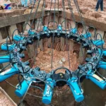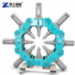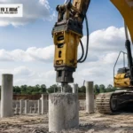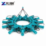
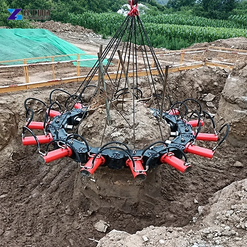
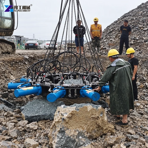
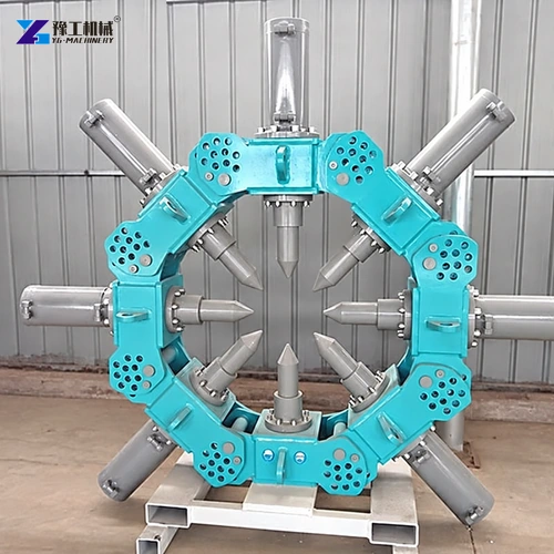
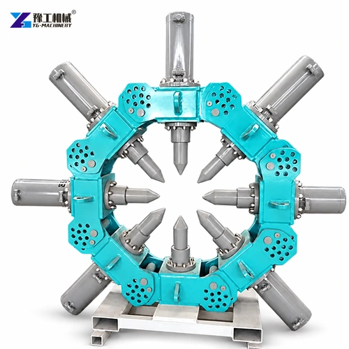
A pile breaker machine removes excess concrete around a prepared pile head by arranging hydraulic modules around the pile. Selection depends on pile shape and measured diameter, module quantity, combined suspended mass, hydraulic supply, lifting equipment and the required cut elevation.
The module matching table maps pile diameter to module count and combined weight. Keep these three fields together when selecting the ring. The site engineer still needs to approve reinforcement protection, exclusion zones, lifting points and the final breaking sequence.
Send the project material, dimensions and working conditions for an initial review.
Measure the Pile Before Choosing Modules
Measure the exposed pile head at the top, middle and planned cut elevation. Record the minimum and maximum diameter, ovality, concrete damage, reinforcement layout and the height of concrete to be removed. The design diameter alone is not enough because cast piles can vary along the exposed section.
Use the largest measured diameter at the working zone to select the preliminary module ring. The modules must close evenly around the pile without forcing the frame out of shape. For tapered, heavily oval or irregular heads, send measured photographs and dimensions before fixing the module count.
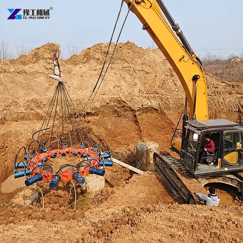
The selected module quantity determines the combined suspended weight and therefore affects the excavator or crane check. Add chains, beam and rigging to the lift calculation, then verify that the carrier can position the complete ring at the actual working radius and cut elevation.
Check Excavator and Lifting Capacity
Combined weight rises from 1600 kg for four modules to 5940 kg for eighteen modules. Review the excavator or crane load chart at the real radius, hook height and working position.
Include chains, lifting beam and rigging in the suspended load. Ground capacity, edge distance and overhead restrictions belong in the lift plan.
| Modules | Pile diameter | Combined weight |
| 4 | 400–600 mm | 1600 kg |
| 8 | 600–800 mm | 2640 kg |
| 9 | 800–1000 mm | 2970 kg |
| 10 | 1000–1150 mm | 3300 kg |
| 12 | 1300–1500 mm | 3960 kg |
| 14 | 1650–1800 mm | 4620 kg |
| 16 | 1970–2200 mm | 5280 kg |
| 18 | 2360–2500 mm | 5940 kg |
Confirm Hydraulic Pile Breaker Inputs
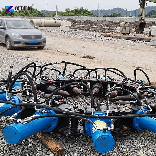
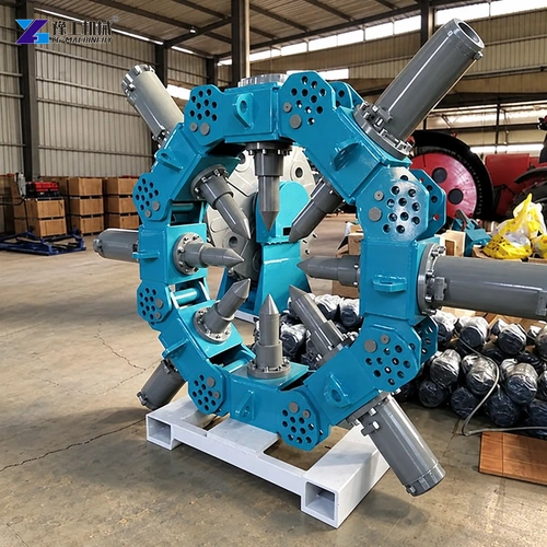
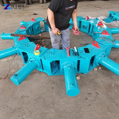
The hydraulic pile breaker uses 300 mm cylinder travel, a 110 mm chisel and a 335 kg single-module weight. These dimensions determine ring geometry, lifting mass and the force position around the pile, so they must be checked together with module quantity and carrier capacity.
Hydraulic flow, pressure, couplings and return arrangement must match the selected power source. Keep hoses protected from pinch points and release stored pressure before connection work.
Plan the Pile Head Breaking Sequence
Mark the approved elevation and expose the working area. Position the ring evenly so modules apply controlled force around the concrete rather than striking one side repeatedly.
Remove broken concrete with a planned handling route and inspect reinforcement and the retained pile. The acceptance standard comes from the foundation design, not from visual speed alone.
Prepare the Pile Breaker Quotation File
Send pile drawings, measured diameter, quantity, concrete and rebar details, cut height, excavator model, hydraulic data, lifting plan, destination and work window.
Request module count, combined weight, hoses, rigging, power-pack option, spare parts, documents, packing and test scope on separate lines.
Provide destination, utilities and accessories for a complete quotation.
Pile Breaker Machine for Foundation Pile Head Removal FAQ
Use the measured pile diameter and the module-to-diameter matching table in this article.
No. Check the real-radius load chart, rigging mass, ground and hydraulic compatibility.
The breaker removes concrete; reinforcement treatment follows the approved project method.
Provide pile dimensions, rebar, cut elevation, quantity, carrier data, lift plan and destination.