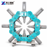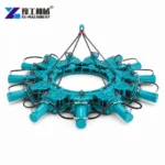
A hydraulic pile breaker removes the unwanted concrete at the top of a pile so the foundation can be brought to its specified cut-off level while reinforcing bars remain available for the next connection. The key configuration decision is the ring of modules around the pile. A ring sized for the wrong diameter will not position evenly, and a machine’s maximum thrust figure does not correct a poor fit.
YG’s published configurations run from 4 to 18 modules and cover listed pile diameters from 400 mm to 2,500 mm. The table identifies each setup by module count, combined weight and diameter band because the page does not publish a separate alphanumeric model code for each combination. The YG hydraulic pile breaker page shows the same product family.
How Does a Hydraulic Pile Breaker Work Around the Pile Head?
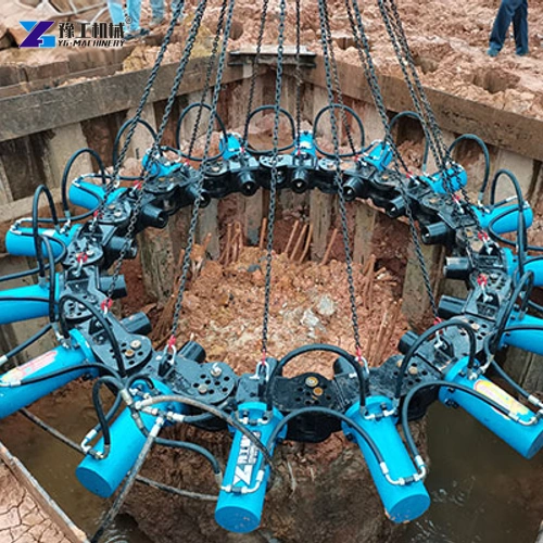
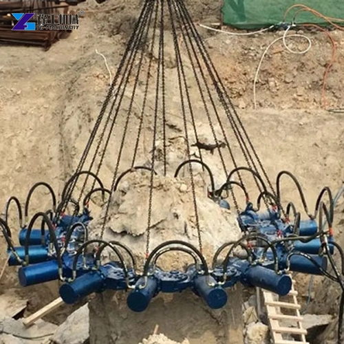
The modules are assembled into a working ring and positioned around the exposed pile head. Hydraulic force operates the module cylinders so the cutting elements act around the circumference. The operator and crew advance the breaking sequence in a controlled manner, remove loosened concrete and inspect the remaining head against the specified cut-off elevation.
This is not the same task as sawing through the reinforcing steel or demolishing the full pile. The objective is to remove surplus concrete while leaving the reinforcement and the designed pile section ready for the pile cap or connection detail. The design drawings and engineer’s acceptance requirements define the final elevation and condition.
The method is useful when a project has a series of pile heads to prepare and the pile geometry fits the available module ring. It is not a universal attachment for every pile shape or reinforcement layout. Confirm exposed diameter, concrete condition, cage position, break level and access before selecting the equipment.

Select Module Count From the Listed Pile-Diameter Band
Measure the actual pile diameter at the level where the tool will engage, not only the nominal diameter on a drawing. A pile can be irregular after excavation or expose a wider concrete head than expected. The selected configuration must surround the pile as designed, with the modules arranged symmetrically and with access for the hydraulic connections and crew.
The YG table pairs 4 modules with 400–600 mm, 8 modules with 600–800 mm, and adds modules as the listed diameter increases. The ranges overlap at boundary values such as 600 mm and 800 mm. Treat those boundaries as a point to confirm with the supplier using the measured pile and exact ring geometry rather than assuming adjacent configurations are interchangeable.
For a diameter beyond 2,500 mm, a non-circular pile or a pile with a special cap shape, the published table does not establish a compatible ring. Request a written configuration decision. Do not create an intermediate model by simply adding modules or extrapolating a diameter band.
A measured diameter and the reinforcement arrangement help identify the correct module ring and reveal whether the published configuration covers the pile head.


YG Hydraulic Pile Breaker Configurations by Module Count
The following are the manufacturer’s listed module combinations. Combined weight increases with module count; confirm the handling method and the carrier or power source for the complete assembly.
| Modules | Combined weight | Listed pile diameter |
| 4 | 1,600 kg | 400–600 mm |
| 8 | 2,640 kg | 600–800 mm |
| 9 | 2,970 kg | 800–1,000 mm |
| 10 | 3,300 kg | 1,000–1,150 mm |
| 11 | 3,630 kg | 1,150–1,300 mm |
| 12 | 3,960 kg | 1,300–1,500 mm |
| 13 | 4,290 kg | 1,500–1,650 mm |
| 14 | 4,620 kg | 1,650–1,800 mm |
| 15 | 4,950 kg | 1,800–1,970 mm |
| 16 | 5,280 kg | 1,970–2,200 mm |
| 17 | 5,610 kg | 2,200–2,360 mm |
| 18 | 5,940 kg | 2,360–2,500 mm |
The manufacturer also lists a maximum thrust of 300 kN, a required cylinder flow of 20 L/min, a minimum excavator tonnage of 20 t, a 35 mm pin, maximum cylinder travel of 300 mm, chisel diameter of 110 mm, single-module weight of 335 kg and module dimensions of 1,015 × 865 × 340 mm. The page groups excavator classes as 20–30 t and 30–40 t without mapping every module count to a specific carrier class; ask the supplier to confirm the recommended carrier for the selected ring.
The listed maximum cylinder pressure is printed as 300 MPa, an unusually high value in this context. It is reproduced as stated, not converted or treated as a validated operating setting. Confirm the hydraulic pressure requirement in writing before connecting the breaker to an excavator or power pack.

Keep the Break Level, Reinforcement and Work Sequence Aligned
Before breaking begins, expose enough of the pile to position the ring at the specified cut-off. Mark the intended elevation and check that the modules can close around the concrete without striking nearby piles, temporary casing, excavation support or reinforcement that must remain. If the bars are bent or tangled, pause and resolve the access issue rather than forcing the ring into place.
The sequence should leave concrete removal and inspection time in the plan. After each controlled operation, remove loose fragments and examine the remaining pile head. Confirm that the concrete is sound at the accepted level and that reinforcement has not been cut or damaged. Follow the project engineer’s requirements for treatment of the final connection surface; the machine’s rated thrust does not define concrete acceptance.
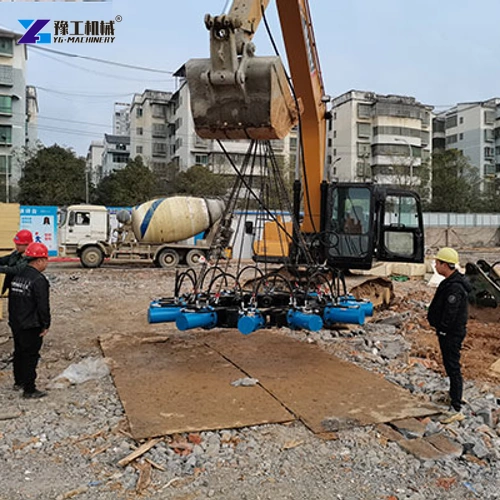
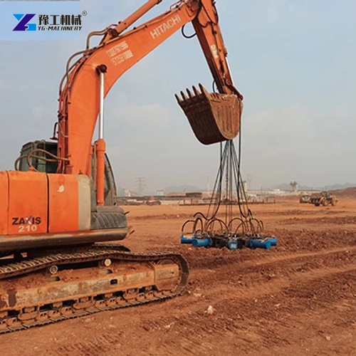
For a building foundation, bridge pier or road and rail structure, crews may face repeated pile heads, but site layouts differ. A tight excavation can limit the excavator’s approach and the space needed to lift or reposition a multi-module ring. Plan the excavator route, hydraulic hoses, lifting aids and spoil removal together so the cutter is not selected in isolation from the foundation sequence.
- Record the measured pile diameter and cut-off level for each pile group.
- Confirm module count, combined weight, carrier class, pin and hydraulic settings as one configuration.
- Protect reinforcement, clear broken concrete and inspect the pile head before the next construction step.
Send the pile diameter range, cross-section, exposed height, cut-off level and excavator model to verify the listed module arrangement and installation details.
Hydraulic Pile Breaker FAQs
The referenced configuration table identifies each setup by module count, combined weight and pile-diameter band; it does not provide a separate alphanumeric model code for every ring. Do not invent one.
YG lists 4 modules for 400–600 mm and 8 modules for 600–800 mm, so 600 mm is a boundary. Confirm the measured pile and correct ring with the supplier before ordering.
The intended pile-head preparation removes surplus concrete while retaining the designed reinforcement for the next connection. It should not be treated as a rebar-cutting tool; follow the drawings and the engineer’s cut-off requirements.
The page lists a minimum excavator tonnage of 20 t and grouped carrier ranges of 20–30 t and 30–40 t. It does not map every module count to a carrier, so confirm the exact configuration, mounting and hydraulics.
The published maximum cylinder pressure is printed as 300 MPa. Because this is an unusual value, obtain written confirmation before using it as a hydraulic setting or comparing it with a carrier circuit.
Match the Ring Before Planning the Breaking Cycle
Choose a hydraulic pile breaker by the measured pile diameter and the manufacturer’s module combination, then confirm the assembly weight, carrier and hydraulic requirements. Keep the cut-off elevation and reinforcement protection tied to the project design; the equipment parameter table is not a substitute for those acceptance requirements.
For a module recommendation, provide the pile dimensions, cut-off level, reinforcement detail and carrier information.