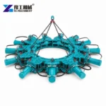
A hydraulic pile cutter—also called a hydraulic pile breaker—is used to remove excess concrete from a pile head at a planned cutoff level. Its modular frame and hydraulic working elements act around the pile perimeter; the attachment does not determine the structural cutoff height or replace the reinforcement plan.
Choose the setup from the pile’s measured shape and size, the required finish, exposed working space and the carrier or power source. Those details determine the module arrangement and help the crew plan how concrete and reinforcement will be handled after breaking.
How Does a Hydraulic Pile Cutter Remove Excess Concrete?
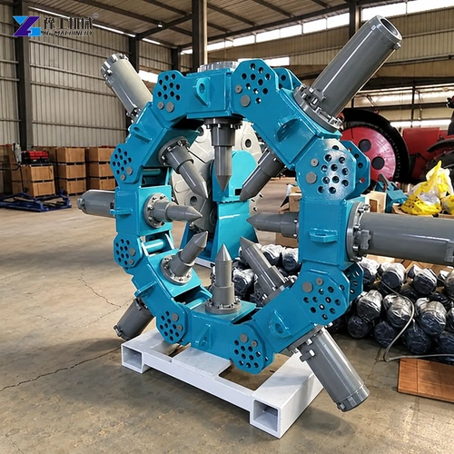
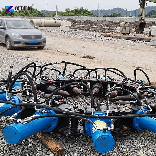
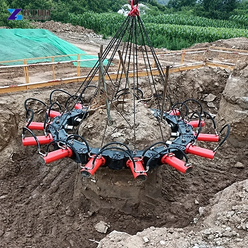
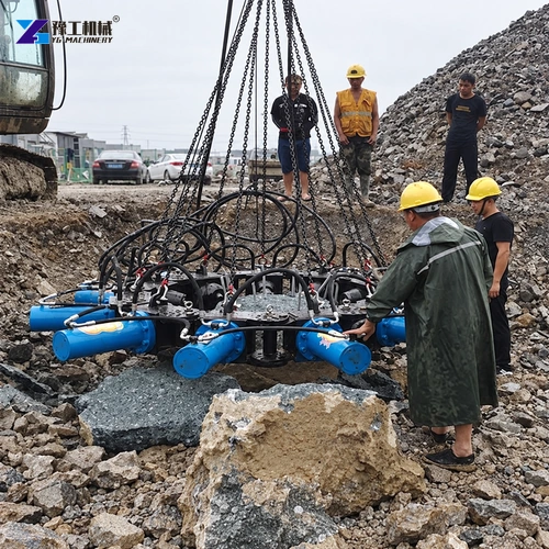
A hydraulic pile cutter uses a modular ring to place working units around the exposed pile head. Once the frame is aligned at the required working height, hydraulic cylinders press the chisels or breaking elements against the concrete around the perimeter; the crew advances through the circumference in a controlled sequence so the excess concrete separates. This is a static-pressure breaking action, not a saw that defines the structural cutoff height.
The work order starts before the attachment arrives: use the structural drawing to establish the cutoff elevation and reinforcement that must remain, expose enough pile for the frame to sit squarely, and clear loose soil or debris from the working band. After breaking, remove fragments without pulling or bending the retained cage, then inspect the pile head against the required level. If the pile is damaged, out of position or unlike the drawing, stop and reassess rather than forcing the same setup.
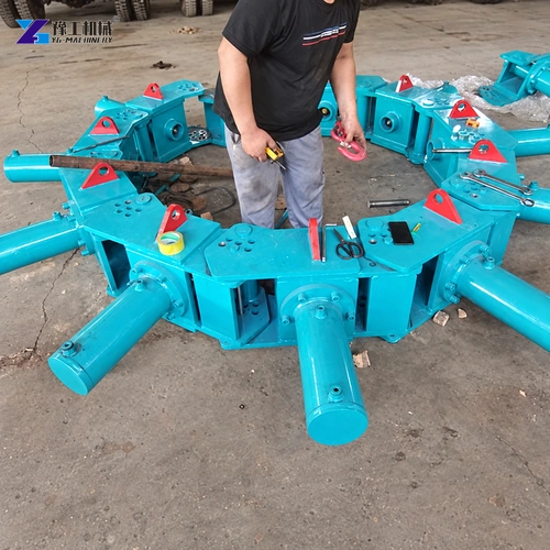
Share the pile profile and cutoff requirement for a configuration check.
CHECK PILE CUTTER FITWhich Hydraulic Pile Breaker Modules Fit the Pile Diameter?
Measure the pile itself at the exposed breaking zone, not from a nominal drawing alone. For a round pile, take diameter readings in more than one direction and check whether concrete buildup or an out-of-round section changes the largest dimension. Select the module-count column whose listed range covers that measurement, then keep its combined weight beside it when checking lifting and handling.
The table gives the published combinations from 4 through 18 modules. It is a sizing starting point for the listed round-pile ranges; it does not confirm fit around a square section, irregular face, crowded reinforcement cage or adjacent pile. For those cases, send a section drawing, actual dimensions and rebar layout so the frame geometry can be checked. The YG hydraulic pile breaker range and the pile-head module selection guide cover the product and selection context.
The official table identifies this pile breaker by module count rather than a separate model code. Each column keeps the published module quantity, total configuration weight and round-pile diameter range together; do not substitute one column’s mass or diameter for another.
| Parameter | Unit | 4 modules | 8 modules | 9 modules | 10 modules | 11 modules | 12 modules | 13 modules | 14 modules | 15 modules | 16 modules | 17 modules | 18 modules |
|---|---|---|---|---|---|---|---|---|---|---|---|---|---|
| Module Number | PCS | 4 | 8 | 9 | 10 | 11 | 12 | 13 | 14 | 15 | 16 | 17 | 18 |
| A combination of the total weight | KG | 1600 | 2640 | 2970 | 3300 | 3630 | 3960 | 4290 | 4620 | 4950 | 5280 | 5610 | 5940 |
| Pile diameter range | mm | 400-600 | 600-800 | 800-1000 | 1000-1150 | 1150-1300 | 1300-1500 | 1500-1650 | 1650-1800 | 1800-1970 | 1970-2200 | 2200-2360 | 2360-2500 |
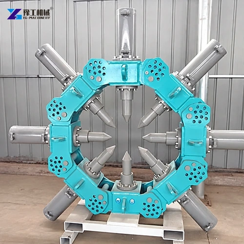
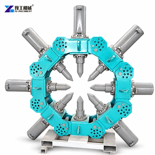
Send the pile-size schedule and required finish so the module layout can be matched.
MATCH THE MODULE LAYOUTWhat Carrier, Access and Lifting Details Affect Pile-Cutter Selection?
First identify how the selected configuration will receive hydraulic power: from the excavator system or a hydraulic power station, as applicable to the proposed package. Confirm mounting, hydraulic connections and the required supply with the supplier rather than guessing from the pile diameter. Then compare the assembled configuration weight with the carrier’s lift capacity at the actual reach where the frame must be positioned.
Walk the route from unloading to every pile: measure ground-bearing conditions, overhead clearance, turning and boom-swing room, and space between neighboring piles. Include the width needed to bring the ring over the exposed head and to remove concrete fragments afterward. If a route narrows or the ground changes, mark transfer and setup points on a site plan; this shows whether the crew can move and reposition the breaker without blocking the next pile.
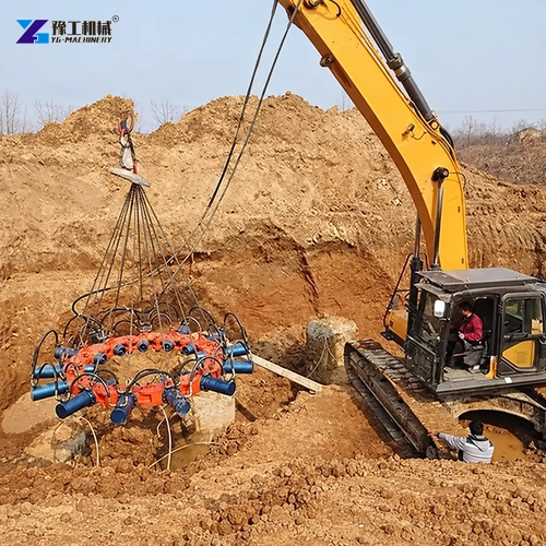
Provide carrier details and site access limits for a hydraulic compatibility review.
REVIEW CARRIER COMPATIBILITYHow Should a Pile-Cutting Cycle Protect the Required Pile Head?
Use a repeatable sequence for each pile. First mark the engineer-specified cutoff level around the pile and identify the reinforcement that must be retained. Expose and clean the working band, measure the pile and cage, choose the matching module arrangement, and place the ring level around the pile. Work around the circumference in controlled increments, checking progress against the mark instead of continuing by time or appearance alone.
As concrete breaks away, clear fragments from the work zone without using the frame to pull the rebar cage. Near the cutoff, slow the cycle and inspect the remaining concrete and steel before completing the pass; the required finish and any final trimming method come from the project specification. For a pile group, plan the order, excavator movements and fragment-removal route before the first pile so finished heads remain accessible and undamaged.
Send your pile layout and target cutoff level for a job-specific quotation.
REQUEST A PILE CUTTER QUOTEHydraulic Pile Cutter and Pile Breaker FAQs
It removes excess concrete from the pile head toward a specified cutoff level. The structural design determines the final level and how the remaining reinforcement is treated.
Match the module arrangement to the measured pile shape and diameter, then check assembled mass, carrier or power source, access and reinforcement clearance.
No. Round-pile ranges do not establish suitability for square or irregular sections. Provide a cross-section drawing and reinforcement layout for a fit assessment.
No. The project drawing and engineer define the cutoff level. Mark that height before breaking and plan the sequence around the required reinforcement.
Send pile shape and dimensions, pile schedule, cutoff level, reinforcement details, carrier hydraulics or power-source requirements, access photos and destination.
A suitable hydraulic pile cutter combines the right module arrangement with the pile drawing, cutoff requirement, power source and access plan.