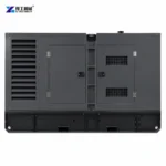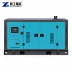
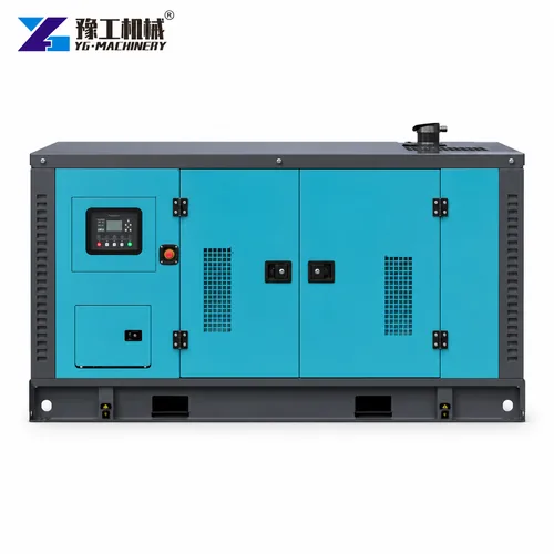
A generator load calculation for a construction site must include more than the sum of nameplate kilowatts. Motors draw extra current during starting, welders and variable-speed drives can distort the load, and several machines may start in the same short interval. Ambient temperature, altitude, phase balance and the acceptable voltage dip also change the usable capacity. A set selected only from continuous running power may stall, trip or create unstable voltage when the largest motor starts.
YG supplies 30–400 kW, 400/230 V, 50 Hz three-phase generator configurations. Those published ratings form a model range, but the correct choice follows the actual load schedule. The calculation below separates running load, starting demand and load steps, then connects the result to verified rated-current values. Buyers should have the final schedule checked against the proposed alternator, engine and control system before ordering.
The worked method is intended to size a YG commercial diesel generator from connected construction loads rather than selecting a set by its largest nameplate motor.
What Data Starts A Generator Load Calculation?
Create one row for every pump, compressor, mixer, hoist, welder, heater, charger, light and control panel. Record input kW or kVA, voltage, phase, power factor, efficiency, starting method, starting current and expected operating time.
Do not convert motor shaft output directly into generator demand without accounting for efficiency. For equipment without a clear plate, request the electrical data from its manufacturer.
Add a simultaneity column. Some loads operate continuously, others cycle, and standby equipment should not be counted as if it runs beside the duty unit unless that is a real scenario. Identify the largest single load and the sequence in which operators start machines. The schedule should represent a normal peak and a credible worst case, not an impossible total where every tool is switched on at once.
Apply diversity only where the work sequence proves that loads will not overlap. Document interlocks or operating rules that enforce the assumption. If the sequence depends on manual discipline, include a credible overlap case rather than hiding risk inside a single percentage.
Send the complete equipment list and operating sequence so the first load calculation assumptions can be checked.

How Are Running kW And Starting kVA Calculated?
Keep the continuous demand and the starting event as separate checks. The first describes the equipment already running; the second tests what happens when the next load is introduced.
Steady Demand On A Consistent kW And kVA Basis
For a balanced three-phase load, apparent power is linked to voltage, current and √3; real power also includes power factor. Use nameplate kVA when it is supplied, because it already reflects the relationship.
For the planning sheet, show units in every column and retain the original nameplate data beside each conversion. Do not silently mix shaft output, electrical input and apparent power. Mark an uncertain input as requiring confirmation; an apparently precise sum does not become reliable when one large load has an unverified basis.
Build the connected-load list from actual nameplates and operating sequences. Separate continuous, intermittent and standby loads. Confirm voltage, phase, frequency, power factor and efficiency so unlike values are not added directly, and identify which equipment truly operates together.
The Largest Credible Starting Event
Add simultaneous running kVA first, then calculate the temporary starting requirement for each motor. Direct-on-line motors may demand several times their running current, while soft starters or variable-speed drives can reduce the step when correctly configured.
Motor starting can control generator selection even when running kilowatts appear modest. Obtain starting method, locked-rotor or measured current and acceleration time. Model the largest credible start while other required loads are running, then check allowable voltage and frequency dip for sensitive controls.
Test the largest likely start while the existing base load is running. If two pumps can start together after a power return, model that event or add sequencing controls. The alternator must tolerate the transient without excessive voltage dip, and the engine must accept the real-power step without a damaging frequency drop. This is why two generator sets with the same headline kW can behave differently on the same motor load.
Send the connected-load list, motor starting data and required operating sequence. YG can review the calculation assumptions before a generator rating is selected.
Provide motor nameplates and starting methods to review the largest transient demand rather than relying only on running kW.

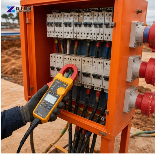
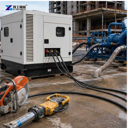
Which Generator Ratings Can Be Used After The Load Is Calculated?
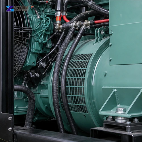
The YG range lists 30, 100, 150, 200, 300 and 400 kW ratings with corresponding currents of 54, 180, 270, 360, 540 and 720 A at 400/230 V.
| Rated power | 30 kW | 100 kW | 150 kW | 200 kW | 300 kW | 400 kW |
| Engine cylinders | 4 | 6 | 6 | 6 | 6 | 6 |
| Voltage | 400/230 V | 400/230 V | 400/230 V | 400/230 V | 400/230 V | 400/230 V |
| Frequency | 50 Hz | 50 Hz | 50 Hz | 50 Hz | 50 Hz | 50 Hz |
| Rotational speed | 1500 rpm | 1500 rpm | 1500 rpm | 1500 rpm | 1500 rpm | 1500 rpm |
| Rated current | 54 A | 180 A | 270 A | 360 A | 540 A | 720 A |
| Phase | Three-phase four-wire | Three-phase four-wire | Three-phase four-wire | Three-phase four-wire | Three-phase four-wire | Three-phase four-wire |
All listed configurations are 50 Hz, 1500 rpm and three-phase four-wire. Compare the calculated steady current with the rated-current column as a cross-check, then verify whether the project needs prime or standby duty.
Do not interpolate a final model from the table without checking the engine and alternator data sheet. Ambient derating, harmonic loads, neutral current, enclosure cooling and future additions can reduce usable margin. If the destination requires 60 Hz or another voltage, the quoted configuration must be changed rather than assuming the 50 Hz table remains valid.
How Much Generator Capacity Margin Is Useful?
Margin should cover measurement uncertainty, acceptable step response, short growth and site conditions; it should not be an arbitrary doubling of the load. Too little margin creates trips and poor transient response.
Excessive oversizing can leave a diesel engine operating at persistently low load, which may increase deposits and inefficient fuel use. The useful margin follows the load profile and the manufacturer’s transient-performance data.
Separate essential and nonessential circuits when a rare peak would otherwise force a much larger set. Automatic load shedding or start sequencing can delay heaters, chargers or a second pump while the critical motor accelerates. A staged plan may reduce installed capacity without compromising operations. Document which loads may be disconnected so site staff do not defeat the strategy later.
Share voltage, frequency, duty, altitude and ambient conditions so the generator configuration can be confirmed.
CONFIRM GENERATOR CONFIGURATION
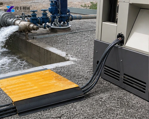
Which Site Conditions And Tests Must Accompany The Rating?
Review step loading, standby duty, ambient derating, enclosure ventilation, fuel autonomy and refueling access. A correct electrical size can still fail the operational requirement if duty and environment are ignored.
Fuel consumption and autonomy should be estimated at the expected load profile, not only at full load. Include storage, refueling, spill control and access. These operating details determine whether the selected set can support the planned shift reliably.
Commission the selected system with staged loads or a suitable load bank and verify protective devices, voltage, frequency, temperature and fuel performance. Retain the tested configuration, cable plan and load schedule so later equipment additions trigger a new review instead of silent overload.
Keep the tested sequence with the equipment list. When the site adds a motor or changes which machines run together, compare the revised event with the original selection assumptions. A spare breaker position or unused steady-state power is not, by itself, evidence that a new starting step is acceptable.
Provide the confirmed voltage, frequency, load profile and site conditions when you need a generator configuration and quotation.
Submit the verified load schedule and installation conditions for a project-specific generator quotation.
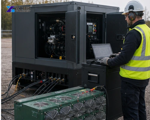
Generator Load Calculation Buyer FAQ
No. Use electrical input and power factor or nameplate kVA, then account for starting demand.
It is the biggest sudden increase in real and reactive demand expected during the operating sequence.
No. Margin depends on starting, site derating, future growth and the generator’s transient capability.
Yes. Starting large motors separately can reduce the required transient capacity.
Request a 60 Hz engine speed, alternator and voltage configuration; do not use the 50 Hz table unchanged.
Provide the load schedule, starting information and site duty below, identifying any figures still awaiting confirmation. YG can review an equipment configuration against that schedule; the responsible electrical professional must verify the final installation and protection requirements.