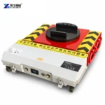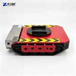
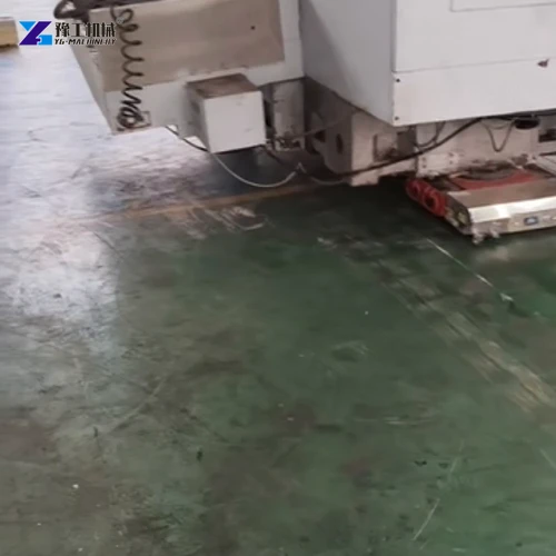
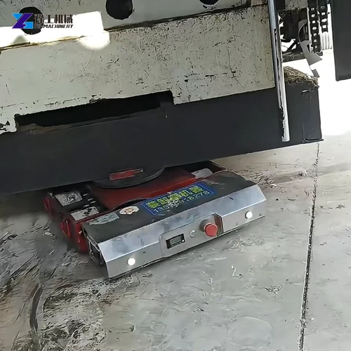
Electric load moving skates provide powered CNC floor travel where the machine’s handling instructions permit the method and its base has suitable structural contacts. The purchasing question is whether the system can support the transport configuration and reach the permanent supports without loading vulnerable panels, disturbing unsecured assemblies or compromising temporary support.
A machining centre is more than a heavy rectangular load. Its casting, moving axes, tool changer and external equipment influence how it must be prepared and supported. The relocation also has two different endpoints: completing the floor move and returning the machine to an acceptable installation condition. Powered travel helps with the first; levelling and the required machine checks complete the second.
CNC Transport Condition Changes The Moving-Skate Requirement
A CNC machine’s operating position is not necessarily its transport position. A table, spindle head or other moving assembly may need a specified position and shipping restraint before relocation. Those requirements keep movable masses from shifting and protect components that were designed for machining rather than for absorbing transport forces. The correct arrangement belongs to the particular machine model.
This affects skate selection because the moving assemblies determine where weight acts on the base. A table carrying a retained fixture adds that fixture’s mass at the table’s transport position. Moving the table or changing what remains on it can change the load reaching the nearby supports. The load carried at each contact is its support reaction. Use the mass and prescribed positions of the actual transport assembly rather than an operating-weight figure without that context.
Loose tooling, coolant equipment and peripheral units also need a defined treatment. Some remain attached and secured; others are disconnected and moved separately. A conveyor projecting beyond the enclosure can influence the swept space even when it contributes little weight. Flexible hoses and cable chains are functional connections, not restraints for an assembly during movement.
Before choosing electric load moving skates, obtain the machine’s transport configuration and permitted handling method. Some machine models prescribe specific forklift pockets or lifting arrangements. A low powered skate is appropriate only where the machine’s construction and handling instructions allow the proposed contacts; the availability of floor clearance alone does not establish that permission.
Send the CNC model and permitted transport arrangement to discuss whether a powered skate package fits that handling method.
Electric Load Moving Skates Must Support The CNC Base Casting
The machine base determines where a moving reaction can enter the structure. A casting may have designated lifting or support areas beneath an enclosure that extends much farther outward. The visible perimeter therefore does not reliably identify a usable contact. A drip tray, cabinet skirt or unsupported cover can occupy the ideal-looking insertion space while offering no suitable load path.
Contact geometry matters as much as access. A small upper pad against an appropriate structural area behaves differently from a pad that bridges an opening or bears on an edge. An extended fabricated member can bend between the contact and the part of the machine carrying the weight. The proposed interface needs to suit both the machine structure and the skate’s support surface.
The support positions determine how that weight is shared. Consider a machining centre whose column and tool changer are concentrated toward one end: the supports there can receive more of the load even if the contacts appear symmetrical beneath the enclosure. Compare each powered or follower support with the weight assigned to its actual contact. Dividing the total equally can understate the load at the heavier end; the assessment needs the specified transport condition and structural contact locations.
For electric load moving skates, the powered unit and passive followers must be evaluated together. Their working heights, support interfaces and individual capacities need to form a compatible arrangement. A larger motor does not correct a poorly supported casting, and an additional roller does not automatically redistribute weight evenly across the base.
Identify the approved casting support areas and their reactions to compare the moving supports.
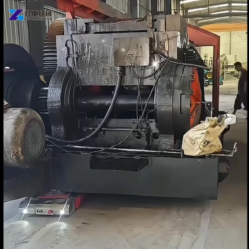
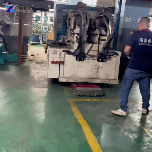
Electric Load Moving Skates Specifications
The YG configurations below offer different chassis sizes and supported-load ratings. They help shortlist a powered component once the machine’s transport weight and individual support reactions have been established. The figures do not assign a rating to an unspecified follower arrangement or authorize a particular CNC handling method.
| YG electric machine skate configuration | 20T | 30T | 40T |
| Powered-unit load capacity | 10 metric tons | 15 metric tons | 20 metric tons |
| Listed towing weight | 20 metric tons | 30 metric tons | 40 metric tons |
| Overall dimensions | 670 × 620 × 165 mm | 740 × 640 × 185 mm | 810 × 800 × 182 mm |
| Motor arrangement | 750 W × 2 | 1200 W × 2 | 1500 W × 2 |
| Battery voltage and capacity | 48 V, 60 Ah | 48 V, 60 Ah | 48 V, 120 Ah |
The 30T unit has a 15-ton supported-load rating; its 30-ton towing figure does not mean that 30 tons can rest on its upper pad. The other supports need to carry their assigned reactions throughout the move. The complete arrangement must also respect the equipment’s permitted operating conditions.
Chassis height is relevant when inserting and removing the equipment. The 30T configuration is 185 mm high, while the 40T configuration is 182 mm high. A higher model designation therefore does not produce a simple progression in every dimension. Compare the actual geometry rather than selecting electric load moving skates from the tonnage label alone.
Compare the 20T, 30T and 40T chassis against the supported reaction and insertion clearance.
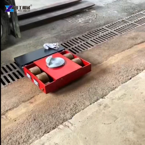
Machine-Moving Skates And The CNC Floor Interface
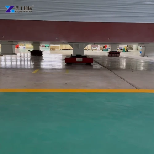
During relocation, the floor receives load through skate wheels rather than through the machine’s normal levelling supports. Their locations and contact areas differ. A slab that has carried the installed machine is not automatically verified for the temporary moving arrangement, especially where the path crosses a cover, joint or a different structural bay.
Surface condition creates another constraint. A wheel meeting a discontinuity can stop while the rest of the system continues to apply force. That resistance passes through the support into the machine. A compliant wheel is not a substitute for a suitable surface, and battery drive should not be used to force equipment across an obstruction or to compensate for an unassessed floor transition.
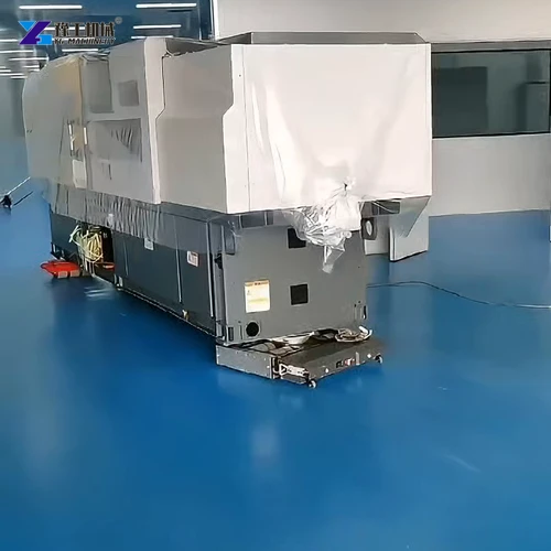
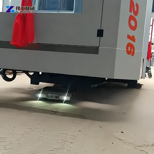
The enclosure can conceal a rear follower or its passage across a floor joint. Observation and communication must therefore cover the complete machine, including the contacts hidden from the front operator’s view. If a support shifts or loses contact, stop movement and use the approved handling procedure to restore support rather than driving against the problem.
When comparing electric load moving skates for an existing factory, distinguish building capacity, wheel contact and machine support. Each is a different part of the same force path. Describing all three helps identify a workable moving package without promising floor protection or machining accuracy from the drive system alone.
From Moving Skates To Levelling Pads And Machine Acceptance
Reaching the new location does not complete a CNC installation. The machine must transfer from temporary rolling supports onto the specified pads, screws or foundation arrangement. Access for removing the skates and lifting equipment has to remain available until the machine is appropriately supported. The final equipment position should allow that transfer rather than trapping a skate beneath an inaccessible corner.
After landing, the permanent pads and levelling screws support the base at the positions intended for machining. These contacts may differ from the temporary skate positions. Changing the distribution of support can change the base’s deflected shape and, with it, the relative geometry of the axes carried by that structure. The installation team therefore checks the machine in its final supported condition, using the manufacturer’s sequence, instruments and acceptance criteria. A level-looking cabinet or an axis that moves under power does not establish machining geometry.
- Complete the controlled transfer onto the designated permanent supports and remove temporary moving equipment as the approved procedure permits.
- Restore the prescribed installation condition, including levelling, anchoring where required and removal of transport restraints at the correct stage.
- Perform the machine-specific geometric, functional and machining checks required before returning it to production. Record the results against the applicable acceptance criteria.
Where the permitted installation method includes suspended placement, mini spider crane selection by load chart addresses the separate lifting-equipment decision. Electric load moving skates should be purchased for their floor-transfer role, with the subsequent installation and acceptance work included in the relocation plan.
Describe the planned landing arrangement to discuss removal access for the moving equipment.
Electric Load Moving Skates FAQs
No. The machine manufacturer must permit the proposed handling method and support locations. Some models require specific lifting points or forklift arrangements, and an enclosure opening does not establish a suitable skate contact.
Use the weight and balance of the actual transport configuration. Attached equipment, retained tooling and prescribed axis positions can affect the total mass and the reaction at each support.
Its powered-unit load capacity is 15 metric tons, while its listed towing weight is 30 metric tons. Other supports require their own suitable ratings and geometry within the complete moving arrangement.
They provide floor movement, not a guarantee of machining geometry. Correct transport preparation, support and handling are necessary, followed by the machine-specific installation and acceptance checks.
That depends on the machine’s transport instructions. Retained peripherals add weight or projections and require suitable restraint; disconnected units need separate handling. Hoses and cables must not be used to hold an attachment in place during relocation.
For a CNC moving equipment enquiry, include the machine model, transport condition, approved support locations, weight distribution and floor-transfer conditions.