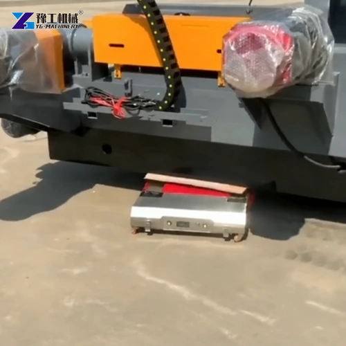
Industrial heavy machine dolly skates can move equipment assembled on a common base, but a shared frame does not automatically make the load rigid. Motors, pumps, gearboxes and process assemblies introduce weight at different positions. Moving supports introduce reactions at other positions. The frame between them must carry those forces without unacceptable distortion.
This distinction matters when an assembly must arrive with its components still correctly supported and ready for alignment checks. The useful question is not simply whether a set of skates can carry the total weight. It is whether the complete transport arrangement suits the baseframe, its mounted equipment and its final installation.
Common-Base Machinery Needs Structural Dolly-Skate Contacts
A common base joins components into one handling assembly. Its longitudinal rails, crossmembers and mounting plates transmit the component loads to the supports beneath it. Those supports may be continuous foundations during operation but only a few temporary contacts during movement. Changing between these conditions changes the way the frame carries weight.
Consider a motor and driven machine mounted near opposite ends of a fabricated skid. During normal operation, several feet may support the rails. During transport, a different support spacing can create a longer unsupported span beneath one component. The frame can bend even though neither component has moved on its mounting bolts. Thin sheet covers and access trays do not provide equivalent structural support.
The permitted handling stations therefore come from the equipment’s construction and handling requirements. An accessible rail is not necessarily suitable at every point along its length. Concentrated contact can also affect a rail locally, particularly beside an opening, weld transition or unsupported plate edge.
Before choosing industrial heavy machine dolly skates, distinguish a purpose-designed transport skid from a base intended mainly for fixed installation. Where the assembly cannot tolerate the proposed temporary support condition, the answer may involve a designed transport frame or another handling method rather than simply higher-capacity skates.
Describe the common base and the assemblies it carries to discuss whether a low moving arrangement fits.
Dolly Skate Positions Change Baseframe Deflection And Reactions
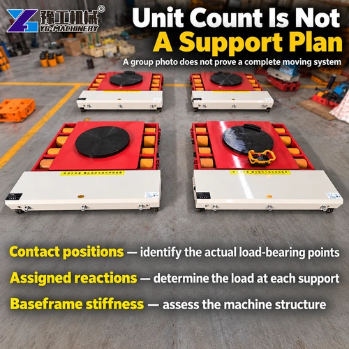
The number and position of supports affect both their individual loads and the deflected shape of the frame. Dividing the assembly weight by the number of skates assumes equal reactions without establishing them. A heavy driven component at one end, an offset vessel or a side-mounted power pack can make that assumption inaccurate.
More supports do not automatically solve the problem. On a frame with limited flexibility, a small difference in support height can redistribute load among several contacts. A support that appears correctly positioned may carry less than expected while another carries more. The transport arrangement needs compatible working heights and a defined method of maintaining the intended load paths.
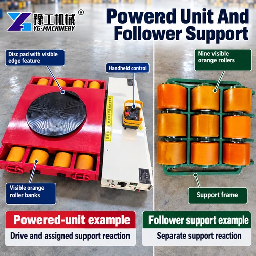
Industrial heavy machine dolly skates should be matched to the reactions established for those particular contact stations. Include any temporary transport frame or retained accessories in the mass assessment. Also distinguish the powered support from follower units: each has its own carried-load limit and its own role in the arrangement.
Baseframe deflection is not only a question of visible damage. A small change near coupled shafts, precision mounting pads or pipe connections may matter before a distortion becomes obvious to the eye. The acceptable support pattern and deflection depend on the assembly; there is no universal span or permissible bend that follows from a skate’s tonnage label.
Identify the structural support stations and permitted frame deflection for the complete assembly.
Industrial Heavy Machine Dolly Skates Specifications
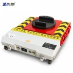
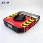
The following YG electric machine skate configurations provide different powered-unit ratings. The towing designation and load carried directly by the powered unit are separate values. Other supports must be selected as part of the complete arrangement, not assumed to have the same specification.
| YG electric machine skate configuration | 20T | 40T | 50T |
| Powered-unit load capacity | 10 metric tons | 20 metric tons | 25 metric tons |
| Listed towing weight | 20 metric tons | 40 metric tons | 50 metric tons |
| Motor arrangement | 750 W × 2 | 1500 W × 2 | 2000 W × 2 |
| Overall dimensions | 670 × 620 × 165 mm | 810 × 800 × 182 mm | 810 × 800 × 182 mm |
| Battery voltage and capacity | 48 V, 60 Ah | 48 V, 120 Ah | 48 V, 120 Ah |
For example, the 20T configuration has a powered-unit load capacity of 10 metric tons. Its towing figure does not permit a 20-ton reaction on the upper support. Likewise, the larger motor in another configuration does not establish that a weak baseframe contact becomes acceptable.
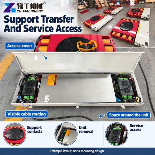
Dimensions affect installation beneath the frame as well as passage through the plant. The 40T and 50T configurations share the listed overall dimensions but have different carried-load and motor ratings. Confirm the supplied contact arrangement and working height when comparing industrial heavy machine dolly skates; an overall chassis dimension is not a complete contact-interface drawing.
Couplings And Connected Components Need Their Own Transport Condition
A common base keeps the mounted components together, but it does not guarantee unchanged shaft alignment. If a rail bends beneath the motor feet differently from the rail beneath the driven machine, the two shafts can change their relative height or angle even though the mounting bolts remain tight. The coupling connects those shafts; it does not make the baseframe rigid. A flexible coupling accommodates its specified operating movements, not unlimited transport distortion. Pipe connections and brackets can also be stressed when their mounting positions move relative to one another.
The equipment manufacturer may require particular transport restraints, disconnection of sensitive links or removal of accessories. Follow the assembly-specific requirements rather than assuming that every bolted component can remain connected. Conversely, unnecessary disassembly can introduce additional work and alignment requirements. The correct boundary depends on the actual assembly, not a standard moving-skate checklist.
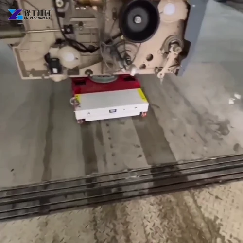
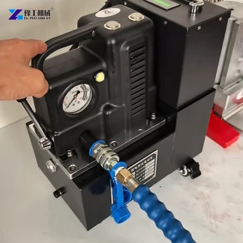
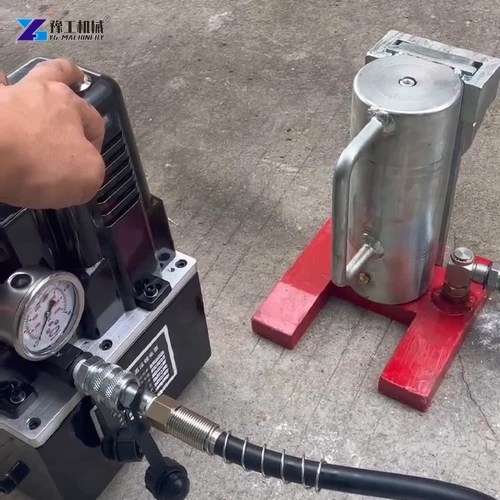
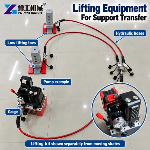
Loading onto industrial heavy machine dolly skates is a separate operation from rolling travel. The lifting arrangement must introduce forces at permitted lifting or jacking points and leave room to install the rolling supports. A pump, jack and moving chassis are not interchangeable devices, even when all are used during the same relocation.
The baseframe handling enquiry should identify where the assembly can be lifted and where it can rest during rolling travel. Those locations need not be interchangeable. Floor-moving capacity cannot be substituted for a lifting rating, and lifting capacity cannot establish an acceptable baseframe support span.
Compare the selected YG unit with its assigned reaction and required working height.
Final Mounting Determines Alignment Acceptance
Landing changes the support condition again. Permanent feet, shims, isolators or foundation interfaces may introduce loads at positions different from the temporary rolling supports. A shaft alignment observed while the assembly remains on skates may therefore differ from the alignment after final mounting.
The receiving arrangement must allow the base to transfer onto its intended supports without trapping the moving equipment or loading sensitive attachments. Where mounting bolts, grout or isolators are specified, their installation sequence belongs to the equipment’s installation procedure. Pulling a distorted base down with bolts is not a substitute for establishing the correct support condition.
- Transfer the assembly onto its specified permanent support locations and complete the required mounting sequence.
- Check level, support contact and the alignment of coupled components in that final condition, using the equipment’s acceptance requirements.
- Restore disconnected connections, remove the specified transport restraints and complete the equipment-specific commissioning checks before operation.
This is the full role of industrial heavy machine dolly skates in a common-base move: temporary supported travel within a wider handling and installation process. A successful journey across the floor is valuable, but it does not by itself demonstrate acceptable shaft alignment or readiness for production.
Describe the permanent mounts and alignment checks required after the assembly lands.
Industrial Heavy Machine Dolly Skates FAQs
The frame must be suitable for the proposed temporary support locations and component loads. A shared base does not automatically provide sufficient transport stiffness or approved contact stations.
Not without establishing the reactions. Component positions, frame stiffness and differences in support height can produce unequal loading, even beneath a visually symmetrical base.
Its listed powered-unit load capacity is 25 metric tons. The separate towing designation is 50 metric tons; these figures describe different duties and must not be interchanged.
Not necessarily. Temporary supports and permanent mounts can produce different frame deflection. Alignment needs checking in the final installed support condition according to the equipment requirements.
Do not assume a powered rolling chassis provides the lifting function required for loading or landing. Suitable jacks, lifting interfaces or suspended-handling equipment must be specified separately where needed.
Send the common-base assembly weight, permitted structural support stations and final mounting arrangement to discuss a compatible powered moving package.