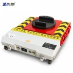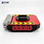
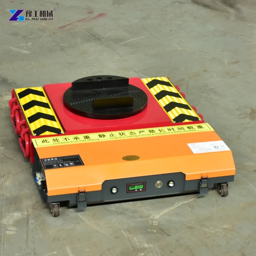

Remote control machine skates move a heavy machine close to the floor while an operator controls its travel from beside the load. Their value is not simply replacing a push with a motor. A powered skate has to transmit enough driving force, carry the reaction at its support point and steer without disturbing the other supports. Those are separate requirements, and a machine that satisfies one does not automatically satisfy the others.
For machinery installers, compare the complete moving arrangement. The driven unit, followers, machine base and floor must work together; model-name tonnage alone cannot establish suitability.
Remote Control Machine Skates: Motor Drive And Steering
The battery supplies electrical energy to a controller, which regulates the drive motors. Reduction gearboxes reduce motor speed and increase torque at the running gear. This allows a compact drive package to produce controlled movement rather than a fast, lightly loaded rotation. The support surface above the chassis carries the machine, while the driven wheels transmit force through their contact with the floor.
Driving and steering are linked but not identical. On a differential-drive arrangement, changing the relative motion of the two drive sides changes the direction of the chassis. The upper rotating support allows the chassis to change heading without requiring the supported machine to turn by the same amount. However, the rest of the load must still be supported and able to follow the intended path. A turning powered unit cannot make an unsuitable follower arrangement behave like an independently steerable transporter.
This distinction matters when moving a long machine tool into position. Its corners sweep a larger area than the powered unit itself. The operator needs to see the whole load, not merely the front of the skate. Slow, deliberate inputs give the crew time to observe the support reactions and the movement of the opposite end. Remote control machine skates reduce direct manual pushing, but they do not remove the need for a competent moving plan.
For a remote-controlled moving-system enquiry, distinguish the movement of the powered chassis from the path of the supported machine. A handset can command the drive unit, but the geometry of the followers determines whether the rest of the arrangement can follow that command.
The driven unit and the rest of the support system must follow the intended movement together.
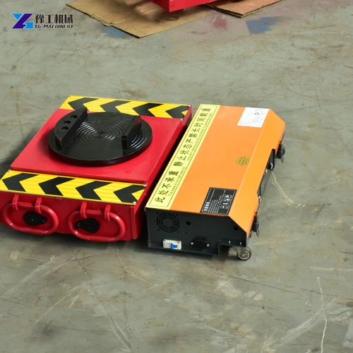
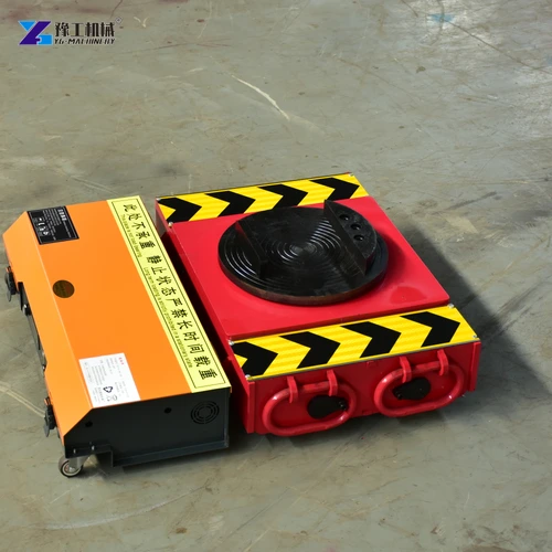
Remote Control Machine Skates Specifications
| Specification | 20T | 25T | 30T |
| Product Configuration | 20T Electric Machine Skate | 25T Electric Machine Skate | 30T Electric Machine Skate |
| Motor And Gearbox | 750W × 2; Braked 104 Flange-Reinforced Gearbox | 1000W × 2; Braked 104 Flange-Reinforced Gearbox | 1200W × 2; Braked Heavy-Duty 120 Flange Gearbox |
| Controller | D2T80A Dual-Channel Driver | D2T100A Dual-Channel Driver | D2T100A Dual-Channel Driver |
| Remote Control | C6/C7 Or Industrial Remote | C7 | C7 |
| Battery | 48V 60Ah; Ternary Lithium Or Lithium Iron Phosphate | 48V 60Ah; Ternary Lithium Or Lithium Iron Phosphate | 48V 60Ah; Ternary Lithium Or Lithium Iron Phosphate |
| Operating Current | 60A | 60A | 60A |
| Towing Weight | 20t | 25t | 30t |
| Load Capacity | 10t | 12.5t | 15t |
| Dimensions | 670 × 620 × 165mm | 670 × 635 × 165mm | 740 × 640 × 185mm |
The towing-weight row and load-capacity row describe different limits. The first is the manufacturer’s moving rating; the second concerns the load carried on the unit. Do not interpret a 30T designation as permission to place that full weight on its upper support. Nor is the moving rating a guarantee for every floor, incline or arrangement of follower wheels. Rolling resistance and the distribution of weight remain important.
Motor power alone is a poor selection shortcut. Chassis dimensions, supported load and gearbox arrangement change alongside the motor package. Unit height affects underside clearance and compatibility with the other supports. A larger drive cannot compensate for incompatible support heights or an excessive reaction.
When comparing remote control machine skates, identify both the total moving mass and the reaction carried by each support. These should be established from the actual machine and its centre of gravity, not by dividing its weight equally because the drawing happens to show an equal number of supports.
Match the supported reaction as well as the total moving weight when selecting the YG configuration.
Powered Skates And Follower Rollers Form One Support System
A powered skate supplies propulsion, but a follower roller normally carries another part of the machine without providing that same drive function. The placement and rating of every support matter. An off-centre heavy component can place substantially more weight on one support than another. The machine’s frame must also be suitable for the chosen contact positions; thin covers, guards and pipework are not load-bearing points.
Three questions clarify the arrangement before equipment is selected:
- Which parts of the machine base are approved to carry its weight? The moving supports must bear against those structural areas, with contact surfaces suited to the task rather than resting against a convenient-looking panel.
- How much reaction reaches each support? The position of the centre of gravity and the support geometry determine this distribution. Additional skates do not automatically share the load equally.
- Can the followers travel through the intended turn? Their wheel orientation, connection and turning behaviour must be compatible with the motion of the driven unit and the supported machine.
Adding nameplate capacities does not establish a safe system. One point can still be overloaded. Load retention and the contact interface need attention; the rotating pad is not a universal fastening system.
Remote control machine skates are especially useful where the load is already supported for controlled floor travel. Getting the machine onto and off that arrangement is a separate lifting task. Suitable lifting equipment and secure temporary support must be selected for that stage; personnel should never reach beneath a machine relying only on a lifting actuator to hold it.
The machine base and follower arrangement determine which support package is suitable.
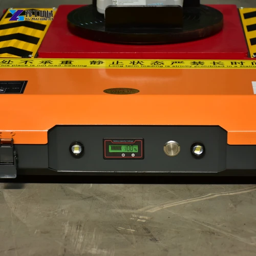
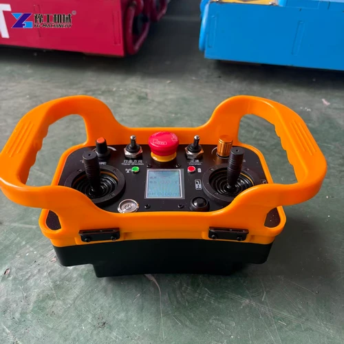
Remote Control Operation Requires A Clear View Of The Entire Load
The operator needs to see the machine, supports and direction of movement. Standing farther away is not safer if it hides the rear support or narrowest clearance. Where visibility is incomplete, use agreed communication and one designated command operator.
Before carrying the load, the specified control functions should be checked in an appropriate unloaded condition. Direction, low-speed response, stop functions and the selected control mode need to be understood. On a system configured for multiple driven units, pairing and coordinated operation must be verified for that actual supplied system. Having a remote that can operate one unit does not prove that an arbitrary collection of units will synchronize.
The follower paths must be established before loaded travel, not discovered by trial steering beneath the machine. A turn that forces a fixed wheel sideways can produce scrub and transmit additional force through its contact. Stop if a skate shifts, a support loses contact or a wheel encounters an obstruction; do not attempt to reseat a displaced support by driving harder. Restore the load to a suitable supported condition through the approved handling procedure.
The supplied stop functions, braking behaviour and response to a lost control signal must be understood for the delivered system. Do not infer a safety-rated emergency-stop function from an unlabelled handset button. Remote control machine skates should not be selected on the assumption that their brakes will hold any load on any slope. Inclines, ramps and suspended floors require assessment of the complete arrangement.
Control mode and visibility should suit the actual machinery-moving operation.
Wheel Contact And Drive Care Affect Controlled Machine Moving
The running gear must develop traction without being damaged by the surface. Loose swarf, small stones and damaged joints can interfere with wheel contact or damage a wheel. A surface that appears smooth may still be unsuitable if it is contaminated, weak or unable to support the concentrated reactions. The floor’s structural capacity is different from its surface finish.
One follower crossing a joint while another remains on smooth concrete changes the forces through the load. Turning also demands different wheel contact from straight travel. An unloaded drive test therefore does not establish suitability for the loaded route.
Inspection should focus on the actual drive path: wheel condition, retained fasteners, gearbox leakage or unusual noise, cable protection and the rotating support. Maintenance intervals and lubricants must follow the supplied machine instructions. Damaged running gear or an abnormal drive response should be investigated before the next move, rather than masked by higher speed or repeated commands.
For remote control machine skates, dependable control requires a matched support system, not just a handset. Select against supported reactions, the moving task and running conditions.

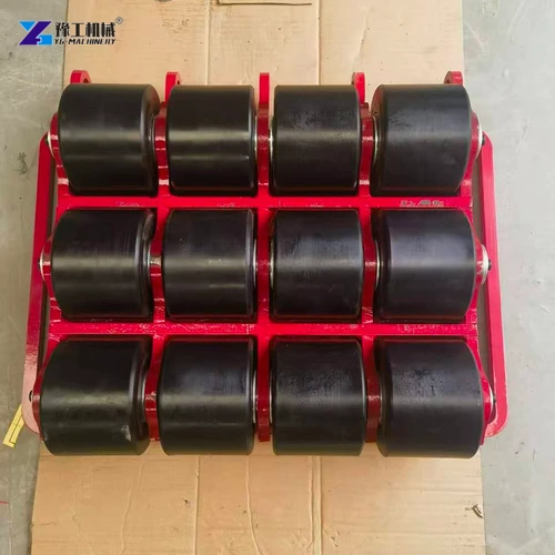
Remote Control Machine Skates FAQs
No. They are separate ratings. The YG table gives a moving rating and a load carried on the unit; both must be checked for the actual support arrangement.
The configurations discussed here are for supported floor movement, not a substitute for a lifting system. Positioning the load requires suitable lifting equipment and secure support.
Follower behaviour depends on its wheel orientation and arrangement. Select it as part of the moving system rather than assuming any passive roller will follow the same turn.
A coordinated multi-unit package must be configured and verified for that purpose. Confirm the supplied control mode and compatible units rather than inferring synchronization from handset appearance.
Not necessarily. A rotating upper support permits relative orientation between chassis and load, while the remaining supports constrain the machine’s path. The complete steering arrangement, not the chassis angle alone, determines the load movement.
Send the machine weight, support-point layout and intended movement to discuss a suitable powered skate and follower arrangement.