Load moving skates are selected as an arrangement beneath a machine, not just as individual wheeled blocks. Fixed supports, steerable units and powered skates solve different parts of the same handling task. The right combination lets the machine follow its intended path while maintaining appropriate contact at every support point.
The most useful comparison is therefore between support arrangements. A fixed-wheel unit can suit straight travel, a steerable support can change heading, and a powered unit can add controlled drive. Choosing among them requires an understanding of wheel direction, load distribution and the way the machine base accepts support.
Fixed Load Moving Skates And Straight-Line Support
A fixed skate has a defined rolling direction. It provides rolling support along that direction and resists being pushed sideways. This can be useful during a straight transfer because the support behaviour is predictable. It becomes a limitation when the same unit is expected to follow a tight turn without being realigned.
The important distinction is between the direction of the wheels and the orientation of the supported machine. A swivel pad above a wheel assembly may allow the chassis to change heading beneath the load. A fixed top and fixed wheels impose different constraints. Buyers should identify which component rotates rather than interpreting every round upper pad as the same steering mechanism.
Rear supports may be supplied with an adjustable connecting arrangement. Such a connection can keep the selected spacing between compatible components, but it should not be assumed to equalize the carried weight automatically. Load distribution still follows the machine geometry, stiffness and support positions. Any claimed equalization feature needs to belong to the actual supplied equipment.
Fixed units are most useful when their wheel direction agrees with the movement expected at that part of the machine. Adding more fixed supports does not automatically improve a system. It can introduce competing directions or create support points that do not share load as intended.
Match fixed followers and their connections to the required straight-line support.
Steerable Skates Change Heading Beneath The Machine
Steerable load moving skates allow a controlled change in the rolling direction. Depending on the design, a turntable, steering handle or powered chassis produces that change. The purpose is to redirect movement while retaining the intended load contact above the skate.
This does not mean every support can follow the same curve unchanged. During rotation, supports at different positions beneath a long machine describe different paths. A rigidly oriented follower may resist the movement expected by the steerable unit. The result can be wheel scrub, increased effort or unintended movement at a contact point.
Consider a long press that must turn before final positioning. The front support may change heading while rear supports travel around a wider or narrower curve. The arrangement must accommodate those paths. A compact steering chassis beneath one end does not describe the space swept by the opposite end or by side-mounted equipment.
The choice is therefore between compatible arrangements rather than a simple fixed-versus-steerable label. For a straight transfer, fixed followers can be appropriate when aligned with the motion. For frequent heading changes, the selected set must provide the required directional freedom at the necessary supports.
A sideways correction is a different motion from a conventional turn. During lateral travel, each support must accommodate that sideways path; turning only the lead chassis does not establish that capability. Any change in support orientation beneath the load belongs to the equipment’s approved handling procedure, not to dragging a fixed wheel sideways until it lines up.
Describe the machine and its required turn to compare compatible steering arrangements.
Wheel Layout, Support Height And Machine Contact
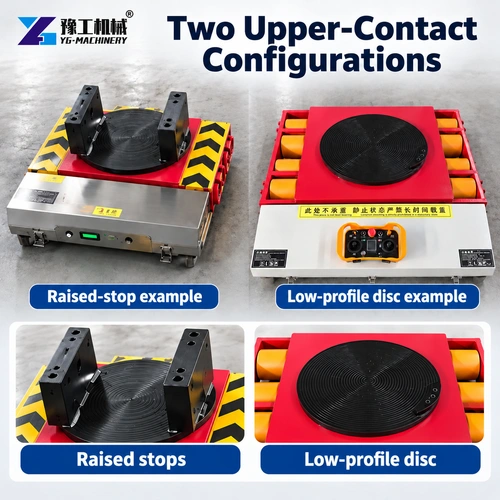
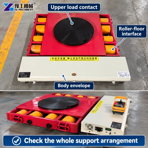
Load moving skates connect the machine base to the floor through several interfaces. At the top is the machine contact. Beneath it are the skate structure, wheel bearings and running wheels. Each interface influences how the supported reaction reaches the ground.
More wheels can distribute a reaction over more contacts, but wheel count alone is not a capacity specification. Wheel dimensions, material, axle arrangement and the supporting structure also matter. An uneven surface may prevent all wheels from sharing load equally. Product photographs can help identify the arrangement, but they cannot establish a model’s rating.
Support height is equally important. If a powered front unit and rear followers have different working heights, a suitable matched arrangement is required. An unplanned difference can tilt the machine or change the reactions. Improvised packing introduces its own questions about stability, contact area and retention; it should not be treated as a routine way to make unrelated components compatible.
- Identify structural support areas on the machine base. Removable guards and thin covers do not provide equivalent support.
- Match the working heights and contact interfaces of the selected components. Include any specified pads or connection parts in that comparison.
- Establish the reactions at the individual supports. Total machine weight divided by the number of skates is not a reliable default for an uneven machine.
These relationships determine whether a set works as one system. They also explain why replacing a single component with a higher-rated but geometrically different unit can make the overall arrangement unsuitable.
Match the support heights and contact areas before combining powered and follower units.
Load Moving Skates Specifications
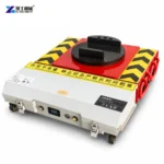
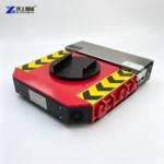
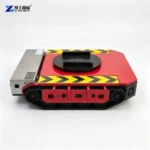
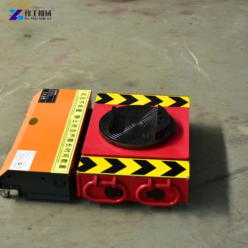
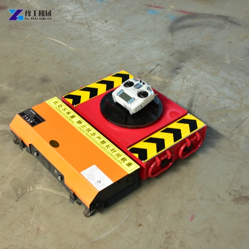
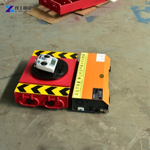
A powered YG unit adds drive to the machinery-moving arrangement. Its upper support carries an assigned reaction while other supports, where required, carry the remainder. The following named configurations illustrate differences relevant to fitting the powered component.
| YG configuration | 20T | 25T | 30T |
| Powered-unit load capacity | 10 metric tons | 12.5 metric tons | 15 metric tons |
| Listed towing weight | 20 metric tons | 25 metric tons | 30 metric tons |
| Chassis height | 165 mm | 165 mm | 185 mm |
| Overall dimensions | 670 × 620 × 165 mm | 670 × 635 × 165 mm | 740 × 640 × 185 mm |
| Motor arrangement | 750 W × 2 | 1000 W × 2 | 1200 W × 2 |
| Battery | 48 V, 60 Ah | 48 V, 60 Ah | 48 V, 60 Ah |
The 20T and 25T configurations share the same listed chassis height, but their carried-load ratings and widths differ. The 30T configuration is taller as well as having a different rating. Changing between them therefore requires more than checking the total moving weight; follower height and machine clearance need attention too.
When comparing load moving skates, keep a powered unit’s towing figure separate from its supported-load figure. These values describe different responsibilities within the arrangement. The table also does not assign a rating to an unspecified follower set. Its components need their own matched specifications.
Compare the 20T, 25T and 30T configurations by carried reaction, height and drive specification.
Selecting A Skate Set For Installation And Repositioning
The equipment package should reflect the directional changes and transfer stages required. A straight approach followed by a small final correction can call for a different arrangement from repeated turns between workstations. Decide which movements the system must perform before selecting components from appearance alone.
Machinery often needs to be raised before the skates can be installed. That stage requires suitable lifting equipment and a controlled transfer onto the rolling supports. In a fixed-and-steerable skate enquiry, distinguish ordinary turns from lateral correction so the proposed set provides the required directional freedom.
Ask the supplier to identify the front unit, followers, any connecting bars and required support interfaces as one proposed arrangement. Include the working height and capacity of each component. An assorted collection of individually strong rollers is not necessarily a compatible moving system.
For ongoing plant use, consider how the arrangement will be inspected, stored and reconfigured between machines. Clear component identification helps prevent a support from one set being combined with a different-height unit from another. Load moving skates provide useful flexibility when that flexibility is supported by a defined equipment combination.
Load Moving Skates FAQs
A fixed unit rolls along a defined direction. A steerable unit allows its rolling direction to change through its particular steering mechanism. The remaining supports must accommodate the path required by that change.
No. A rotating pad concerns relative orientation between the support and chassis. Powered movement requires a drive system. Confirm the actual construction and functions of the selected equipment.
They require a suitable matched support arrangement. Unplanned height differences can tilt the machine or change reactions. Working height, contact interfaces and any specified adapting components should be agreed for the complete set.
Not generally. The machine’s centre of gravity and structural support positions affect individual reactions. Unequal loading can overload one component even when the combined nominal capacities appear sufficient.
No. The powered unit’s towing and carried-load ratings are separate, and neither assigns a rating to an unspecified follower. The other supports need their own suitable capacities and compatible geometry.
Describe the required straight travel, turns and lateral corrections, together with the machine contacts and working height, to discuss a compatible skate arrangement.