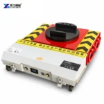

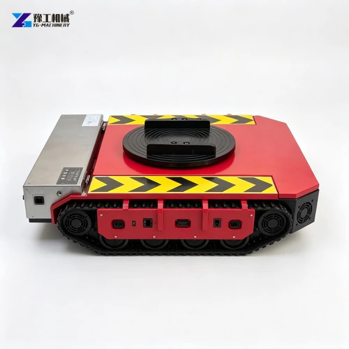
Battery-powered load-moving skates provide motor-driven travel beneath a supported transformer. They can be considered for the floor-transfer part of an installation or relocation when the transformer’s base and the running surface suit the chosen moving arrangement. The battery supplies propulsion; the base and supports carry the equipment’s weight.
The transformer’s base is the first interface to understand. Base channels, original rollers and designated jacking points do different jobs, and the final plinth may accept the unit differently from the temporary moving supports. This guide concerns a de-energized transformer in its specified transport condition; electrical disconnection and commissioning remain separate specialist work.
Transformer Base Channels and Original Rollers Meet Moving Skates Differently
The base carries the transformer’s assembly into its supports. On one unit, structural channels may provide designated transport contacts; on another, original rollers provide the intended means of ground movement. These arrangements lead to different equipment selections because a powered pad needs a permitted bearing surface, whereas an existing roller already defines a contact with the running surface.
Three features need to be identified separately:
- Structural base channels. A designated bearing area can transfer weight into a powered pad or a specified adapter. The pad’s size and position must provide the intended contact. Resting only on a channel edge changes that interface, even if the moving unit has enough nominal carrying capacity.
- Original transformer rollers. These belong to the transformer’s handling design and can have a specified running direction or wheel-orientation procedure. A proposed powered arrangement must work with that design. The presence of rollers does not make a nearby enclosure surface a new support point.
- Jacking pads and lifting lugs. These apply load during particular lifting tasks. Their location helps plan how the transformer is loaded or unloaded, but they are not interchangeable with a moving-skate seat. Each interface must retain its intended function.
Once the bearing interface is established, the skate dimensions can be checked against the available space. The wheel-type configurations below provide one set of comparisons; a crawler-type proposal needs its own construction-specific data. The following load discussion then establishes the weight that those contacts must carry.
Compare the transformer’s base channels, original rollers and lifting provisions to identify the moving-equipment interface.
Battery-Powered Load-Moving Skates Specifications
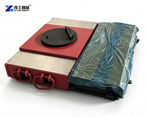
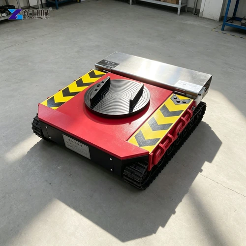
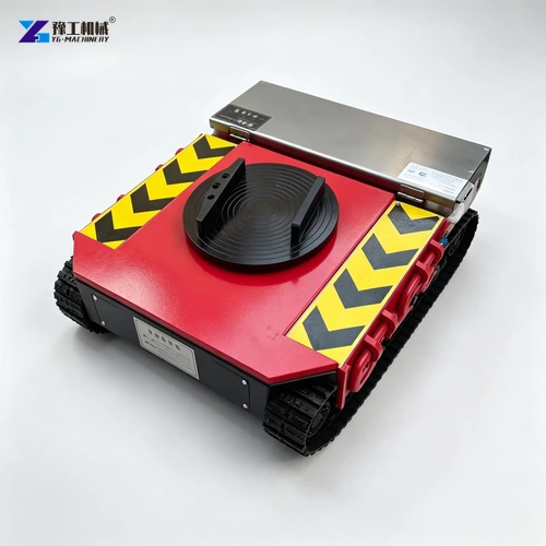
The table lists named wheel-type YG configurations. Several photographs show crawler-type variants from the moving-equipment family; their ratings and dimensions are separate and are not established by this table. Select the actual supplied construction against its own specification.
| Parameter | YG 10T Configuration | YG 25T Configuration | YG 60T Configuration |
| Model designation | 10T | 25T | 60T |
| Towing weight | 10 metric tons | 25 metric tons | 60 metric tons |
| Powered-unit load capacity | 10 metric tons | 12.5 metric tons | 30 metric tons |
| Geared motors, with brakes | 500 W × 2 | 1,000 W × 2 | 3,000 W × 2 |
| Dual-channel driver | D2T80A | D2T100A | D2T220A |
| Listed remote-control options | C7 remote | C7 remote | C7 or industrial remote |
| Listed operating current | 25 A | 60 A | 120 A |
| Battery voltage and capacity | 48 V, 30 Ah | 48 V, 60 Ah | 48 V, 120 Ah |
| Battery options | Ternary lithium | Ternary lithium or lithium iron phosphate | Ternary lithium |
| External dimensions | 500 × 550 × 145 mm | 670 × 635 × 165 mm | 1,110 × 800 × 185 mm |
The 25T configuration has a listed powered-unit load capacity of 12.5 metric tons. That is the carrying value to compare with the weight on its pad; 25 metric tons is its separate towing designation. Accompanying supports need their own ratings for their assigned loads.
Dimensions determine whether a unit can be inserted and recovered at the intended base contacts. The listed unit height is only part of the required space: the contact arrangement, any approved adapter and the loading method also matter. Motor power and battery capacity describe the drive package, not a universal runtime, grade limit or stopping distance.
Compare the reaction at the powered support and available insertion space with the named YG configuration.

Transformer Transport Weight and Balance for Battery-Powered Skates
The relevant load is the transformer assembly that will actually move. A dry-type unit inside its enclosure differs from a bare core-and-coil assembly, while an oil-filled unit’s shipping and operating conditions can also differ. The manufacturer’s transport condition identifies the retained components and fluids whose mass must be carried.
The kVA rating describes electrical capacity rather than physical mass. Enclosure construction, cooling equipment and accessories explain why transformers with similar electrical duties can require different moving equipment. Selection therefore needs the transport mass of the actual unit, not a mass inferred from another model’s electrical rating.
Retained accessories affect balance as well as total weight. A cabinet or cooling assembly mounted to one side can increase the load carried at the contacts on that side. In practical terms, the load at a support is the portion of the transported assembly borne there. It need not equal total mass divided by the number of supports. Transport drawings and the specified bearing locations establish the basis for comparing those loads with the carrying values in the table.
The equipment proposal should accommodate that assembly rather than assume that enclosure parts can be removed or oil drained to fit a smaller skate. Such changes alter the transformer itself and require the applicable manufacturer procedure. With the assembly and bearing locations fixed, travel can be assessed without changing the basis of the capacity comparison midway through the move.
Identify the transported assembly and the weight at its bearing contacts to match the powered unit’s carrying value.

Battery-Powered Skate Travel During Transformer Relocation
During travel, the powered unit supplies propulsion while the followers carry their assigned portions of the transformer. The assembly’s height, projecting accessories and support spacing all remain part of the move. A low chassis does not make the carried transformer a low-profile load; its full outline and balance determine what must be observed during changes in motion.
Three parts of the journey deserve particular attention:
- Starting and stopping. The drive must suit the loaded arrangement and the supplied control functions. Motor power by itself does not establish smooth response or a stopping distance. Avoid treating a successful unloaded run as evidence of behavior with the transformer aboard.
- Floor transitions. A joint or local step reaches different supports at different moments. This can change rolling resistance and disturb the assembly rather than merely slow the leading unit. Compare the complete path with the selected wheel or crawler construction’s permitted surface conditions; greater motor power does not make an unsuitable transition acceptable.
- Turning with followers. The supports can follow different paths as the assembly changes direction. Observation and communication must cover the whole transformer and its followers, not just the powered chassis. Electronic synchronization is a separate configured capability, not something established by using several units together.
Wheel-type and crawler-type designs make different floor contacts. Claims about protection, obstacle crossing or maneuverability require the selected construction’s operating information. Once the travel arrangement is suitable, the final issue is how the transformer leaves it and reaches the permanent support.
Describe the rolling conditions and required direction changes to assess the configured powered moving arrangement.

Transferring a Transformer From Moving Skates to Its Plinth
Placement changes the transformer’s support from temporary moving units to the foundation or plinth specified for installation. Permanent rollers, anchoring provisions or vibration-related components may form part of that support. The installation drawing defines the intended arrangement.
The plinth creates a specific access question. Its raised edge or a recessed bearing area can prevent a temporary unit from being withdrawn in the same direction it entered beneath the transformer. The receiving design must accommodate both the permanent bearing positions and the space occupied by the moving units until unloading is complete. Original rollers, if retained, must meet the installation arrangement specified for that transformer.
After placement, the transformer follows its installation checks and qualified electrical work before energization. This separates three understandable stages: supported floor travel, transfer to permanent support and preparation for electrical service. Each has its own equipment and responsibilities.
Use the YG contact page to discuss the moving configuration with the actual transport assembly, base contacts and receiving arrangement. These details allow carrying capacity and chassis fit to be assessed for the floor-transfer task.
Battery-Powered Load-Moving Skates FAQs
No. Electrical capacity is not transport mass. Selection needs the actual manufacturer’s defined transport condition, mass and support reactions, together with the permitted handling contacts.
Not automatically. Integral rollers and separate moving skates have different interfaces. The transformer handling provisions must permit the proposed support locations and movement arrangement.
No. Its listed towing weight is 60 metric tons and its powered-unit load capacity is 30 metric tons. The complete supported arrangement needs separate assessment; the towing figure is not the carrying value.
Use the mass of the actual manufacturer-approved transport assembly, including its retained accessories and fluids. Shipping and operating figures can describe different conditions. Do not assume that removing equipment or draining oil is an acceptable way to fit a moving-unit rating.
No. Floor movement, transfer to permanent support and electrical commissioning are separate stages. The supplied moving unit must be evaluated for its defined role, without assuming lifting, installation or energization services are included.
For a transformer-moving equipment enquiry, provide the equipment designation, manufacturer-defined transport condition and mass, approved base contacts, existing rollers or jacking provisions, and receiving support arrangement. YG can evaluate the powered moving unit against those interfaces.