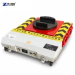
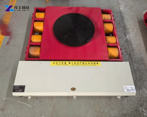
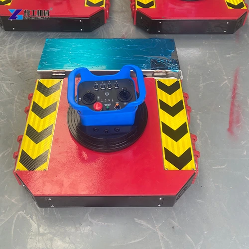
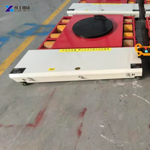
An electric machinery moving dolly provides powered floor travel beneath a supported machine. For an injection molding machine, the challenge is not simply its overall weight: the clamping assembly, injection unit and attached equipment place different loads along the machine bed. The dolly and its accompanying supports need to carry that actual transport assembly.
The long machine bed is the link between those assemblies. Its transport contacts, moving components and installation feet determine how a powered dolly can be used. A useful selection therefore considers the bed as a structure carrying several assemblies, rather than treating the injection machine as a compact block of one quoted weight.
Injection Molding Machine Loads for an Electric Moving Dolly
The transport load is the machine in the condition in which it will actually move. It may be a complete assembly or a manufacturer-defined section of a larger machine. The relevant weight includes the components retained in that condition, not an operating-force label or the weight of the mold alone.
An injection molding machine has two substantial working assemblies. The clamping side closes and holds the mold; the injection side prepares and delivers the plastic material. Their positions along the bed help explain why the weight may not be evenly shared between front and rear supports. The center of the enclosure is therefore not a reliable guide to balance.
Clamping tonnage describes force used in production, whereas a moving dolly is selected against transported mass and the weight at its support. Likewise, a retained mold or hopper changes the assembly being moved. Establish the machine manufacturer’s permitted assembled or sectional transport condition before comparing equipment capacities; separating a machine requires its own approved provisions.
A machine moved with its injection unit attached can present a different balance from a manufacturer-defined transport section containing mainly the clamping assembly. The moving supports must suit the chosen assembly, including a retained mold where permitted. The transport drawing identifies that assembly and its support loads; these are the inputs for comparing the powered units below.
Identify whether the machine will move assembled or in manufacturer-defined transport sections to discuss the appropriate powered moving arrangement.
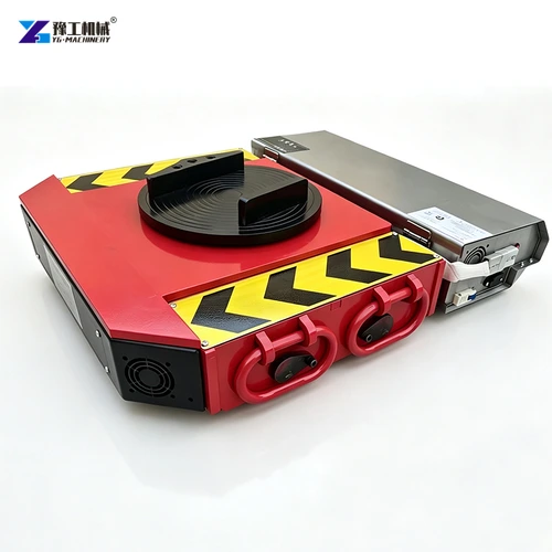
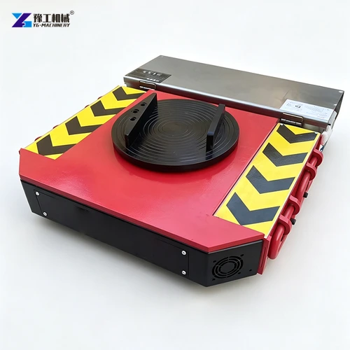
Electric Machinery Moving Dolly Specifications
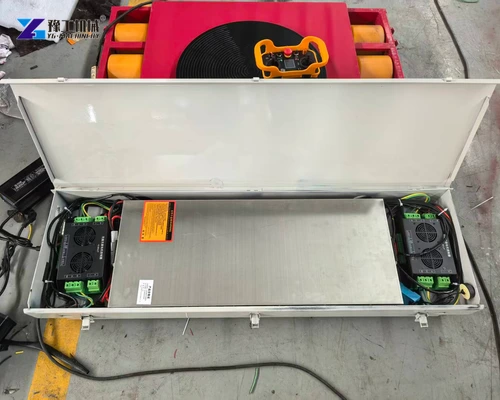
The YG configurations below separate the powered unit’s own carrying capacity from its towing designation. Read carrying capacity against the weight assigned to its pad, then check dimensions against the space available beneath the machine bed. Drive and battery values describe the electrical package for that configuration.
| Parameter | YG 25T Configuration | YG 30T Configuration | YG 50T Configuration |
| Model designation | 25T | 30T | 50T |
| Towing weight | 25 metric tons | 30 metric tons | 50 metric tons |
| Powered-unit load capacity | 12.5 metric tons | 15 metric tons | 25 metric tons |
| Geared motors, with brakes | 1,000 W × 2 | 1,200 W × 2 | 2,000 W × 2 |
| Dual-channel driver | D2T100A | D2T100A | D2T200A |
| Listed remote-control options | C7 remote | C7 remote | C7 or industrial remote |
| Listed operating current | 60 A | 60 A | 120 A |
| Battery voltage and capacity | 48 V, 60 Ah | 48 V, 60 Ah | 48 V, 120 Ah |
| Battery options | Ternary lithium or lithium iron phosphate | Ternary lithium or lithium iron phosphate | Ternary lithium or lithium iron phosphate |
| External dimensions | 670 × 635 × 165 mm | 740 × 640 × 185 mm | 810 × 800 × 182 mm |
The 30T configuration lists a powered-unit load capacity of 15 metric tons. Its towing designation of 30 metric tons is not permission to place that entire weight on one pad. Other supports carry their assigned portions of the machine and need suitable individual ratings.
The listed 25T and 30T units also differ in height and footprint, despite both offering 48 V, 60 Ah batteries. This is why selecting a larger towing designation is not a simple drop-in upgrade: its chassis, pad position and accompanying supports must still fit the machine. The next check is where those contacts meet the bed.
Compare the supported reaction and insertion envelope with the named YG moving configuration.
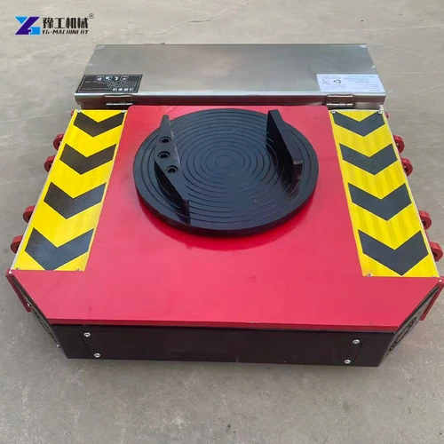
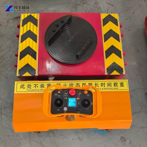
Supporting a Long Injection-Machine Bed During Dolly Travel
The bed carries the clamping and injection assemblies while maintaining their structural relationship. During relocation, its weight passes into the floor through temporary moving contacts instead of its normal installation feet. The position of those contacts matters because a long bed spans between them. A convenient gap below a cover is useful only if it leads to a designated structural bearing area.
Three details need to agree:
- Structural contact beneath each assembly. A permitted bed contact transfers the local load into the moving support. Covers, cable trays and guards have different functions. Placing a pad beneath one of these parts can load the enclosure while leaving the intended bed contact unsupported. The proposed pad must both reach and seat on the designated area.
- Load sharing along the bed. The clamping assembly, injection unit and retained tooling do not necessarily have the same mass or occupy symmetrical positions. A support nearer the heavier portion can receive a greater share of the load. This is why the powered pad’s rating must be compared with its assigned load, not with total weight divided by the number of dollies.
- Compatible heights across the support layout. The powered unit and followers together establish the bed’s supported position. If one contact is too high, it can receive load before the others seat; if too low, it may not take its intended share. Adding a support is therefore a change to the support layout, not an automatic improvement. Use the machine’s specified transport contacts and the corresponding support design.
These relationships explain why a long injection machine may need a different dolly arrangement from a compact machine of equal mass. The selected moving equipment must carry the bed at the right locations while leaving room for the loading and unloading equipment. Next, the components attached to that bed must remain in the transport positions used to establish its balance.
Locate the permitted machine-bed contacts and expected reactions before selecting powered and follower supports.
Securing an Injection Machine Before Powered Dolly Travel
The moving platen and injection carriage travel during production, but that freedom of movement is undesirable during a relocation. A change in their position can alter the distribution of weight along the bed and move a projecting component into the surrounding space. The manufacturer’s transport positions and restraints keep those assemblies in the condition for which the support arrangement was selected.
Attached equipment affects more than the total mass. A barrel can project beyond the moving supports, a hopper can increase the assembly’s height, and a robot or conveyor can have a support separate from the main bed. Each retained item changes the outline that must pass through the workshop. Items requiring removal or independent support follow their own manufacturer procedures; supporting the bed does not support every accessory automatically.
Services form the other part of preparation. Cooling lines, power and material-handling connections must be addressed under the machine’s relocation procedure before travel. The handset controls the dolly’s movement; isolation and reconnection are machinery-service tasks carried out through their appropriate procedures.
With the assembly secured, services prepared and bed correctly supported, the electric machinery moving dolly supplies the travel force through its driven running gear. Floor transitions, turns and follower resistance affect that moving duty. They are evaluated for the prepared assembly, rather than addressed by choosing a larger motor to compensate for incorrect support or loose equipment.
Describe the prescribed positions of the injection and clamping assemblies to define the actual transport load.
Transferring an Injection Machine From Dollies to Its Installation Feet
Temporary bed contacts are selected for transport, whereas installation feet or mounts support the machine in its operating position. They may act at different locations. The receiving arrangement must therefore allow the intended feet or mounts to take the weight without trapping a moving unit beneath an inaccessible part of the bed.
For example, a machine standing on several designated feet can require access at more than one point along its length. A dolly positioned where an installation foot needs to be fitted creates a different problem from a dolly that can be withdrawn beside that foot. Compare the transport-contact drawing with the installation-support layout before selecting the unloading equipment. The resulting clearance must allow the temporary supports to leave while the installation feet take their intended positions.
After weight has transferred to the specified installation supports, the machine follows its leveling, service-reconnection and recommissioning procedures. The important distinction is physical: the dollies carried the transported bed, while the installed supports establish its operating condition. A successful powered move preserves that transition rather than treating arrival at a floor mark as the whole installation.
A useful injection-machine moving enquiry identifies the machine model, its transport condition and mass, and the permitted bed contacts. These describe the machinery that must be supported, with the supported load and installation contacts assessed together.
Electric Machinery Moving Dolly FAQs
Use the machine’s transport mass and permitted support arrangement. Clamping tonnage describes an operating force, not the weight that the moving equipment must carry.
Its powered-unit load capacity is 15 metric tons, while its towing weight is 30 metric tons. Each contact in the full moving arrangement needs a suitable rating for its actual reaction.
The permitted support arrangement depends on the machine design. Select the powered and follower supports from the approved contacts and reactions rather than assuming one upper pad can support the complete bed.
Use the machine manufacturer’s specified transport condition. Retaining or removing the mold changes the assembly being moved, so its mass and securing requirements must match the chosen condition.
The machine still needs its specified installation supports, restoration of services and recommissioning checks. Moving equipment provides transport, not proof of production readiness.
For an injection-machine moving enquiry, include the machine designation, permitted assembled or sectional transport state, transport mass, approved machine-bed contacts and intended receiving supports. This helps match the powered dolly with the actual transport assembly and receiving supports identified.