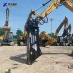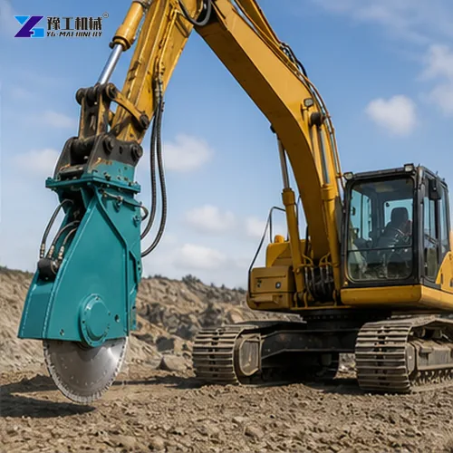
A rock cutting attachment should be selected around the shape of the material removal. A circular rock saw makes a relatively narrow cut along the blade path. A drum cutter uses multiple picks across its working head to remove material over a broader area. Both cut, but they do not create the same excavation result or leave the same material-handling task behind.
This difference is useful when comparing equipment for trench boundaries, rock profiling or controlled removal around a foundation. A narrow saw cut can define a boundary without removing the whole volume inside it. A drum cutter can progressively remove that volume, but it is not simply a wider version of the same saw pass. The finished geometry and the following removal operation should decide the comparison.
A Rock Saw Defines A Cut Plane
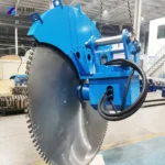
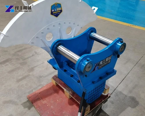
The rotating blade concentrates its cutting action along a narrow path. As the excavator positions and advances the attachment, the blade creates a kerf through compatible material. The cutting element, drive and support arrangement must be suited to the intended material and the supplied machine. Not every blade is interchangeable between natural rock, concrete and other substrates.
The important geometric result is the cut plane. Parallel cuts define the sides of a strip, while intersecting cuts can divide a mass into sections. The blade removes material along its kerf rather than across the entire area between those planes. Plan the cut pattern with the method of detaching and handling the resulting sections: this is where boundary cutting differs from excavating a complete volume.
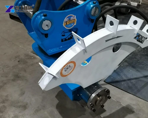
Blade access also controls where the cut can reach. Disc diameter, mounting and the excavator’s movement determine the accessible cutting area: how deeply the blade can enter and which positions it can reach without the guard or attachment body contacting the surrounding material. A catalogue depth does not mean that every corner or orientation is accessible at that depth. The planned cut should account for the physical body of the attachment as well as the blade path.
Describe the boundary cut and how the material between cuts will be removed.
A Drum Cutter Removes A Working Face
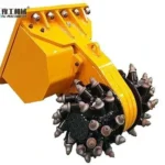
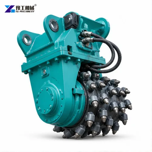
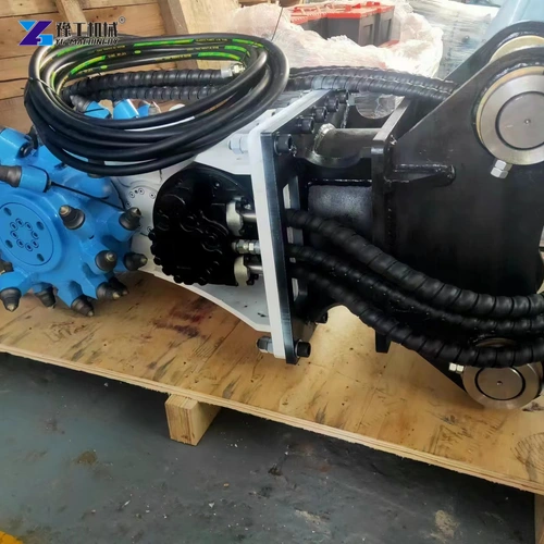
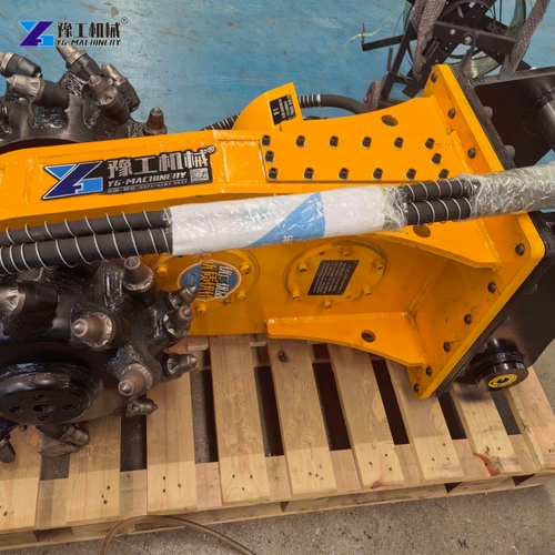
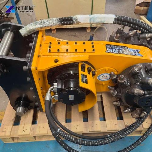
A transverse drum cutter brings several cutting picks into repeated contact with the material. The working head moves across the face, removing material progressively rather than creating only one narrow slit. This can suit surface profiling and the reduction of a defined excavation volume where the material and carrier match the cutting system.
The picks, holders and drums form a different wear system from a saw blade. Successive picks contact the face as the drums turn, so pick condition and how much of the head engages the material influence cutting action. The excavator moves the head across the intended surface. Use the approved technique to control engagement; the cutting head is not a lever for prying partly detached blocks.
The removed material also occupies the working area. It needs a route away from the face so that the cutter is not repeatedly working through accumulated spoil. The useful production rate therefore depends on cutting and clearance together. A faster rotating head does not solve a removal route that prevents access to fresh material.
Identify the face shape and the volume to be removed progressively.
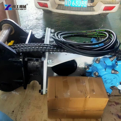
YG Rock Saw And Drum Cutter Parameters
The YG-CF2 disc range is 1.2–1.6 m, with a listed maximum cutting depth of up to 800 mm. Usable depth depends on the selected disc and the space occupied by the hub, guard and mounting; the maximum is not a depth rating for every disc in the range. Specify blade diameter and usable depth together for the required cut. The YG140 drum cutter has a different working geometry: its head width and diameter describe a rotating face-cutting tool rather than a saw cut. These configurations illustrate different cutting methods, not equal-capacity alternatives.
| Parameter | YG-CF2 rock saw | YG140 drum cutter |
| Excavator reference range | 6–9 t | 5–10 t |
| Published cutting element dimensions | Disc diameter 1.2–1.6 m | Head width W 410 mm; diameter D 390 mm |
| Published cutting width | 9 mm kerf | Not a saw-kerf specification |
| Published maximum cutting depth | Published maximum: up to 800 mm; blade/mounting pairing to be specified | Not stated as a saw-style depth |
| Hydraulic flow | 80 L/min | 40 L/min |
| Additional published drive data | Pressure 30 MPa | Maximum power 22 kW; speed 0–120 rpm |
The similar carrier-weight ranges do not make these attachments interchangeable. Their hydraulic requirements, mounting, working envelope and removal methods differ. The excavator must be assessed with the actual attachment and working position, not selected only from the overlap in carrier tonnage.
The excavator rock saw and drum cutter range provide the related equipment routes. For a saw, disc diameter and mounting clearance influence accessible cut depth, while kerf describes the narrow strip removed by the blade. For a drum cutter, head width describes the lateral working span and drum diameter describes the rotating head. Successive passes develop the excavation profile; drum diameter is not equivalent to a saw’s maximum cut depth. Compare those geometric functions before comparing power or carrier class.
Compare the actual carrier and hydraulic supply with each named configuration.
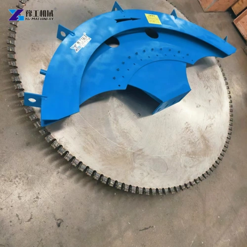
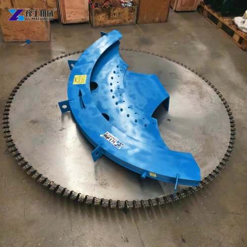
Four Excavation Tasks And Their Cutting Requirements
- Defining a trench edge. A saw can establish a narrow boundary cut where the blade and mounting can follow the required line. The material inside the trench still needs a separate removal plan; the edge cut alone does not create the trench volume.
- Profiling an exposed rock face. A drum cutter can progressively work a wider surface toward the required profile. Access for the head and clearance of loosened material help determine whether the proposed arrangement suits the face.
- Dividing material for later handling. Saw cuts can divide a mass into defined sections where the cut pattern, material behaviour and subsequent detachment method are appropriate. The lifting or removal plan remains separate from the cutting attachment’s specifications.
- Removing irregular projections. A drum cutter may suit progressive removal over uneven areas where a sequence of narrow planar cuts would leave substantial intervening material. The actual material strength, abrasiveness and inclusions still influence tool selection and achievable cutting behaviour.
These tasks can also occur at different stages of the same excavation. For example, a defined outer edge may be cut before the interior is progressively removed and cleared. Where the specification calls only for profiling an exposed face, adding boundary cuts may create extra positioning and handling without improving the required surface. The required shape determines which operations add value; maximum power alone does not resolve that choice.
Match The Cutting System To The Actual Material
Rock strength is only part of the material description. Abrasive minerals wear cutting elements even where the rock breaks relatively easily. Joints and bedding can let material detach along existing planes, changing the shape and size of pieces to be handled. A massive, unjointed face can respond differently from fractured material with the same general rock name. Describe strength, abrasiveness and structure separately instead of relying on the label hard rock.
For a saw, discuss the blade specification and its intended material with the equipment supplier. For a drum cutter, discuss the pick and holder arrangement and how the face will be engaged. Reinforcement or foreign metal should be identified explicitly rather than assuming that a tool intended for natural rock can cut every inclusion.
A representative demonstration can link the material to the desired result. For the saw, examine the cut geometry and the remaining material-removal task. For the drum cutter, examine the achievable profile, spoil condition and tool wear over the trial. Observing the finished result is more informative than comparing two short videos filmed in unidentified materials.
Compare The Complete Cutting And Removal Cycle
Compare a full working sequence from positioning to cleared excavation. For a saw-based route, include the cut lines, repositioning between planes and the subsequent detachment and handling of sections. For a drum-based route, include progressive face cutting and removal of accumulated spoil so the head reaches fresh material. Record cutting time, repositioning time and clearance time separately. This shows whether progress is limited by tool engagement, excavator access or the removal of loosened material, and makes the comparison about the same finished excavation rather than unlike individual passes.
Dust, fragments, cooling arrangements and exclusion zones should be addressed for the supplied equipment and site. The controls must match the actual cutting method and material; they cannot be inferred from the attachment’s compact size. The operating manual and site method should define safe inspection and tool replacement after isolation.
When requesting a rock cutting attachment, provide the required excavation shape, material information, carrier data and the next removal step. Ask the proposal to identify the blade or pick configuration, mounting, hydraulic requirements and service parts. This connects the purchase to the work it must complete, not to a generic claim that one cutting method can replace every other tool.
Send the excavation shape, material information and next handling step for a defined offer.
Rock Cutting Attachment FAQs
Not with one narrow kerf. It defines a cut along its blade path; the material between boundary cuts requires an appropriate detachment and removal method.
No. Drum width describes part of the working-head geometry. A saw-depth figure describes another aspect of the cutting envelope and cannot be substituted for it.
Possibly, but carrier weight alone is insufficient. Check the actual hydraulic supply, mounting, attachment load and working position for each proposed configuration.
Abrasiveness, joints, bedding, reinforcement and other inclusions affect tool selection and the way the material is cut and removed.
It should show the required geometry in representative material and the subsequent removal task, with the offered blade or picks and the proposed carrier arrangement.
Send the excavation drawing, material information, carrier model and removal method to discuss the saw or drum-cutter configuration.