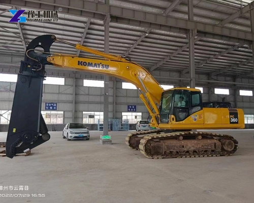
An excavator metal shear separates steel by closing a cutting jaw against a supporting jaw. The useful comparison is not simply which machine has the largest mouth. A wide opening helps capture a section, while the section’s shape, blade contact and position in the jaw influence the actual cutting task. A hollow tube and a solid piece with the same outside dimensions do not present the same resistance.
For a scrap processor or a contractor reducing decommissioned steel, the jaw must suit both the section being cut and the intended contact position. The steel-to-jaw relationship helps narrow that choice; the hydraulic shear buying guide covers the mounting and equipment-package details that follow.
An Excavator Metal Shear Produces Different Force Along the Jaw
The hydraulic cylinder drives the moving jaw through the attachment’s linkage. That movement creates a turning effect around the jaw pivot. The blades then concentrate force on the material between them. The jaw is therefore both a lever and a cutting assembly, not a pair of flat plates that delivers an identical force at every point.
For the same closing moment, a contact nearer the pivot can develop more force than one farther away. Think of the distance from the pivot to the steel as a lever arm: increasing that distance requires more turning effort to produce the same contact force. The linkage also changes geometry during closure. The blade contact position therefore matters alongside cylinder force: moving the contact changes the lever arm and the closing geometry.
The front of a jaw can help engage or pierce suitable material, while the main blade region performs its designed shearing function. Those roles depend on the supplied jaw. They are not permission to force any object into the deepest available space or use the attachment as a pry bar. The permitted cutting zone and material orientation belong to the actual shear’s operating instructions.
The intended cut must suit the part of the jaw performing it. An outside-opening dimension alone misses this relationship.
Compare the required cutting position and section with the actual jaw design, not just its widest opening.
Steel Plate, Hollow Sections and Beams Engage a Metal Shear Differently
The shape being cut determines how much material the blades encounter and how it can move during closure. Section dimensions need to describe that shape, not reduce everything to a single diameter or thickness. These three common material groups illustrate the difference.
- Plate and flat fabrication offcuts. The blades engage the steel along a progressing cut. Plate thickness, material grade, the amount engaged and the free shape of the offcut influence resistance. A broad, thin offcut may bend or curl as it is separated; that deformation is not the same requirement as producing a precise fabrication edge. A scrap shear is selected for separation and reduction, not assumed to replace a precision plate-cutting process.
- Pipe and hollow structural sections. Outside size determines whether the section can enter the jaw, but wall thickness describes a different part of the load. The section can flatten or change shape as the jaws close, so a mouth that accepts its diameter has not established cutting capacity. A square tube adds corners and flat walls to that engagement. The proposed cut needs the actual section and grade, not a comparison based only on the empty space inside it.
- Beams, channels and built-up sections. Flanges, webs and adjoining plates create more than one local thickness. Their orientation changes which parts the blades encounter together. A beam’s overall depth is therefore not a solid-steel cutting thickness, and its web thickness does not describe every part of the section. Welded attachments or nested pieces can further change the cut from the clean standard profile shown in a drawing.
Bundled or tangled scrap creates an additional distinction across these groups. Several individually small pieces can engage together and move differently from one straight sample. A successful demonstration on a loose thin offcut is not evidence for a tightly packed bundle. A trial on the intended bundle or section shows how its shape and contact position affect separation.
Include the steel profile, dimensions and grade so the proposed jaw can be evaluated against representative material.
Excavator Metal Shear Specifications
The YG-620, YG-1413 and YG-2200 entries below show why machine size, opening and working geometry should be read separately. The stated opening is not a chart of permissible steel thickness, and the carrier range does not replace an installation and stability assessment.
| Parameter | YG-620 | YG-1413 | YG-2200 |
| Attachment weight | 620 kg | 1,413 kg | 2,200 kg |
| Maximum opening | 334.4 mm | 540 mm | 500 mm |
| Effective shear depth | 286 mm | 348 mm | 486 mm |
| Overall width | 864 mm | 1,175 mm | 1,370 mm |
| Overall height | 1,521 mm | 2,050 mm | 2,380 mm |
| Listed working pressure | 235 bar | 300 bar | 320 bar |
| Applicable excavator-weight range | 5–9 t | 10–19 t | 20–25 t |
The YG-2200 has a greater listed shear depth than the YG-1413, but a smaller opening. This is a concrete example of why a heavier attachment should not automatically be described as having a larger mouth. Depth, opening and mass describe different characteristics of the equipment.
Working pressure belongs to the hydraulic match, not a setting to raise until a cut succeeds. Flow, return conditions and installation still need checking for the selected attachment. The excavator shear attachment range gives the wider model context. None of these entries provides lifting approval.
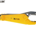
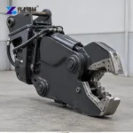
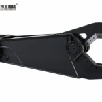
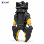
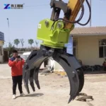
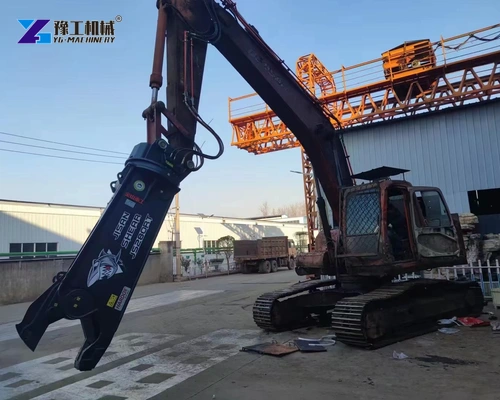
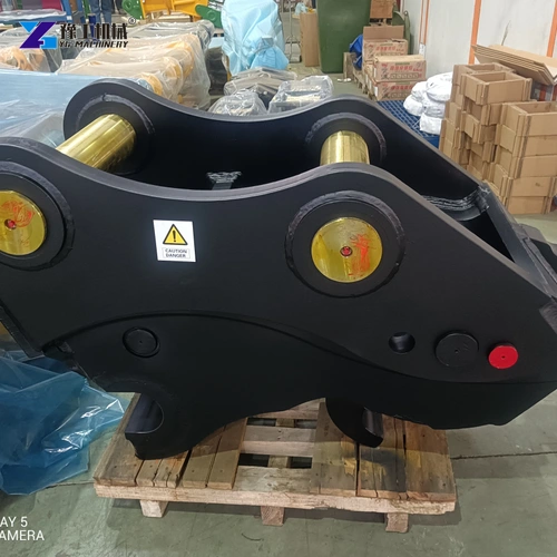
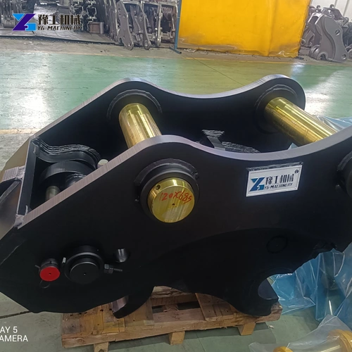
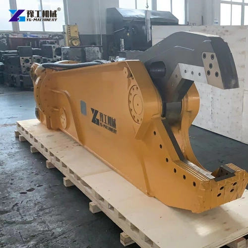
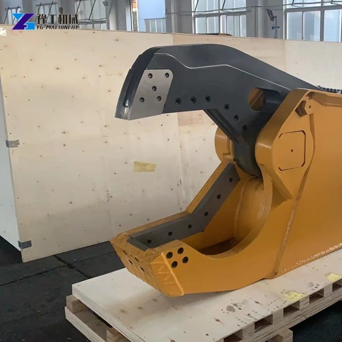
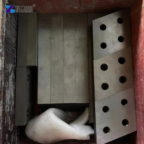
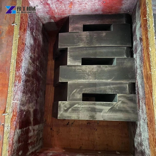
The workshop photographs show several jaw and mounting designs. Differences in their pivots, brackets and blade arrangements matter when selecting service parts; a broadly similar appearance does not make those components interchangeable.
Match the named YG model to the carrier and hydraulic circuit before choosing its installation package.
Blade Edges, Seats and Jaw Guidance Work as One Cutting Assembly
An excavator metal shear needs controlled blade engagement as well as closing force. The moving and supporting cutting components act together to separate the steel. If the material is mostly being squeezed, folded or pulled sideways instead, more closing force may increase deformation without producing the intended cut.
Blade condition is one part of that behavior. A rounded edge spreads contact over a larger area instead of maintaining the intended cutting edge, so more movement can go into deforming the steel. Seating and retention are another part: the blade needs firm support in its designed position for the opposing edges to engage correctly. Movement in a damaged seat changes that relationship. The supplied design determines whether blades can be indexed, which edges are usable and which replacement parts belong together.
Jaw guidance also matters. The cutting structure must resist the side forces generated during engagement. Wear at relevant pivots, guides or supporting surfaces can alter the relationship between the blade paths. A blade replacement alone does not establish that a worn jaw assembly has returned to its specified condition.
This is why a service package should identify more than a box of generic knives. The useful items are the correct blade set, retainers and associated wear components for the actual shear. Inspection limits, blade clearances and repair methods must come from that machine’s instructions. Values or welding practices from another attachment are not transferable merely because both products cut steel.
Excavator Metal Shear Trials and Cut-Piece Handling
An excavator metal shear should produce pieces that suit their next handling stage, not merely demonstrate that a section separates. A scrap container has a loading opening and usable space; a transport arrangement needs pieces that can be supported and secured; further processing may accept only a particular form of feed. The trial should therefore compare the resulting length, shape and projecting ends with the actual receiving task as well as record the cut itself.
Cutting and handling remain different operations. A long section can change balance as it separates, and one end may still be attached to a larger assembly. The work plan must establish support, separation and receiving arrangements. An attachment’s ability to sever a sample does not establish the stability of the excavator or the behavior of an attached structure during demolition.
A useful comparison trial therefore uses representative steel and records what the machine actually did: the section and grade, the supplied jaw and blades, the completed separation and the resulting piece. Repeated results on the intended material are more informative than a video of an unidentified offcut. The trial is conducted under the manufacturer’s procedures, not by increasing hydraulic settings beyond the approved configuration.
For decommissioned pipe or vessel work, the material must first be confirmed suitable for mechanical cutting by the responsible team. Closed, pressurized, contaminated or structurally loaded items cannot be treated as ordinary loose scrap. Identifying the metal shape is part of selection; identifying the item’s condition is a separate safety responsibility.
Jaw geometry, steel shape and blade condition explain an excavator metal shear more accurately than one force number. Capture, cutting and lifting capacities must remain separate in the equipment comparison.
Define the representative cut and the resulting piece so the equipment proposal addresses the actual reduction task.
Excavator Metal Shear FAQs
No. Opening describes entry geometry. Section shape, wall or plate thickness, grade, blade engagement and the permitted cutting configuration determine a different question.
A contact farther from the pivot requires more closing moment to develop the same force. Linkage geometry also changes as the jaw closes. The permitted cutting zone and representative steel section therefore belong in the comparison, alongside the hydraulic and blade specifications.
Its hollow section can deform during jaw closure. Outside diameter and wall thickness describe different parts of that engagement, so the actual section needs to be evaluated with the intended shear.
Not necessarily. Blade seating, retention, jaw guidance, pivots, material and the hydraulic match can also affect engagement. Inspection must consider the complete cutting assembly.
Cutting capability does not provide lifting approval. The receiving and handling method must be established separately for the attachment, carrier and piece under the permitted procedures.
Include the carrier, material section, grade if known and the intended separated piece. Identify whether blades, mounting parts, hoses and commissioning support are required in the equipment scope.