A hydraulic concrete pump uses pressurized oil to drive the mechanism that moves concrete. The oil supplies motion; the concrete travels through a separate material circuit. This distinction explains why engine size, hydraulic pressure and concrete delivery pressure describe different parts of the machine rather than three interchangeable measures of pumping ability.
For a contractor comparing pumps, the useful question is how the drive moves material through the selected pumping mechanism. A twin-cylinder S-valve design is one common layout explained below. The compact electric YG-10 is compared later by its fine-aggregate range, output and physical size. Hydraulic drive and concrete distribution are separate design choices: the drive supplies motion, while the distribution assembly connects the material cylinders to the delivery line. For delivery into the forms and coordination with the crew, see the small concrete line pump placement guide.
The Two Circuits Inside a Hydraulic Concrete Pump
The hydraulic circuit transfers power from the motor or engine to the moving mechanisms. A hydraulic pump supplies oil flow, and control valves direct that flow to cylinders or hydraulic motors. In a piston-type concrete pump, the concrete follows a different route: from the hopper through the material cylinder and outlet into the delivery line. The oil drives the motion; the material piston displaces the concrete.
In a twin-cylinder pumping design, the hydraulic drive moves two concrete pistons in an alternating cycle. As one material piston retreats, concrete enters its cylinder from the hopper. The other piston advances and pushes its charge toward the delivery line. The alternating movement allows successive charges to enter one conveying line instead of waiting for a single cylinder to fill and empty before starting again.
That cycle is easiest to understand as three linked actions:
- Filling. A retracting material piston creates the receiving space for concrete from the hopper. A consistent supply of suitable concrete helps the cylinder fill properly.
- Delivery. The advancing piston displaces the charge into the outlet path. Resistance from the material and line is reflected in the load on the drive.
- Changeover. The drive and distribution arrangement switch roles at the appropriate point, so the newly filled cylinder takes over delivery.
In this twin-cylinder layout, filling, delivery and changeover form a repeating sequence. Poor filling means the next stroke has less material to displace; changing over faster does not recover the missing charge. Delivery resistance loads the drive as the advancing piston pushes material into the line. These relationships explain why output depends on both the pumping mechanism and the concrete supplied to it, not engine size alone.
Identify the material and working cycle so the drive and pumping assembly can be discussed together.
S-Valve Distribution in a Twin-Cylinder Concrete Pump
In an S-valve layout, a shaped distribution tube connects the delivery outlet alternately to the two material-cylinder openings. Its movement accompanies the change in piston roles. One cylinder is connected to the delivery path while the other can receive material from the hopper. The valve is handling abrasive concrete, not simply directing clean hydraulic oil.
The S-tube must meet the active cylinder opening closely enough to direct the concrete charge into the delivery path. In designs using a wear plate and cutting ring, these parts form the contact interface around the material opening. Wear or damaged contact surfaces can reduce sealing effectiveness, allowing material to escape the intended delivery path and reducing useful displacement. These concrete-contact parts therefore have a different job from the hydraulic valve that redirects oil to the actuators.
For buyers, the practical distinction is between the machine’s control equipment and its material-handling hardware. An electronic control panel commands the working sequence; it does not replace the physical sealing and wear components. A complete hydraulic concrete pump proposal should identify the actual distribution assembly, compatible service parts and the access needed to maintain them.
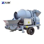
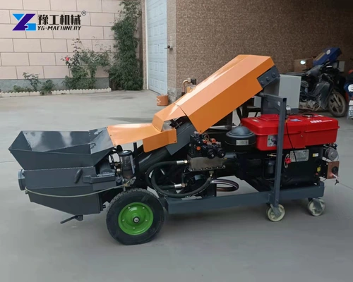
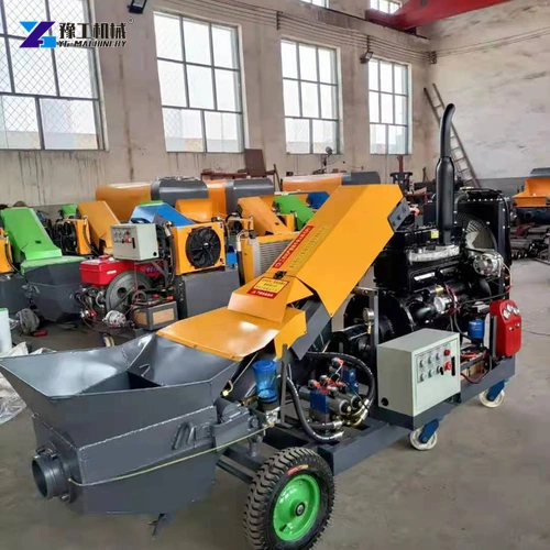
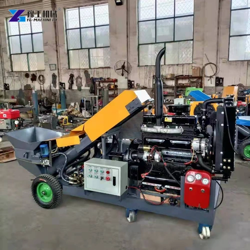
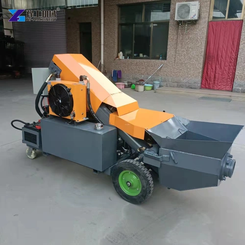
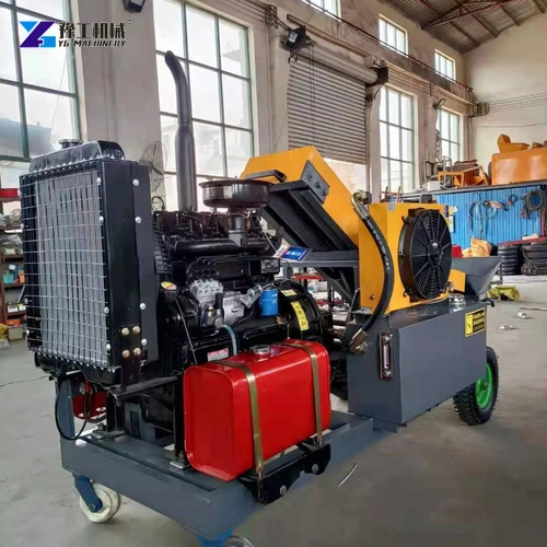
In an S-valve package, the tube, its actuator and the concrete-contact wear parts work together through each changeover. Access to those components affects inspection and replacement work. The illustrated diesel-drive machines show the external arrangement; the electric fine-aggregate unit below is a separate configuration.
Include the distribution valve and compatible concrete-contact service parts in the proposed package.
Hydraulic Concrete Pump Specifications
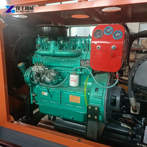
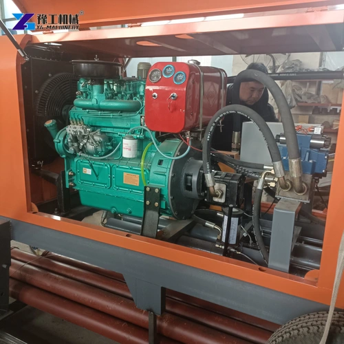
The YG-10 is an electric fine-aggregate configuration. Its motor power describes the drive input, while the aggregate-size entry and delivery-pipe diameter describe material and connection requirements. Output, material size and pipe connection together establish the first comparison with the receiving task. The distribution assembly and its service components are specified separately for the selected pumping mechanism.
| Parameter | YG-10 electric configuration |
| Motor power | 15 kW |
| Listed output | 6 m³/h |
| Aggregate-size entry | 0.5–1.5 cm |
| Delivery-pipe diameter | 80 mm |
| Listed vertical conveying distance | 20 m |
| Listed horizontal conveying distance | 50 m |
| Machine weight | 600 kg |
| Dimensions | 1,800 × 700 × 1,100 mm |
The output figure describes material delivery, while motor power describes the drive input. Neither is an efficiency percentage or an electrical-consumption guarantee. A machine can encounter a high delivery resistance without producing its highest possible flow at the same time. The operating envelope, concrete and complete delivery system determine the usable combination.
Likewise, the two distance entries are separate catalogue conditions, not a route that combines both limits. The 80 mm pipe entry identifies a size, but couplings, hose construction and component pressure ratings still have to match the supplied pumping package. The electric concrete pump guide covers the supply-side considerations for that drive choice.
Compare the compact electric configuration with the material and delivery package your pour requires.
Hydraulic Drive, Oil Cooling and Material-Piston Care
The hydraulic system needs oil clean enough for its pumps, valves and seals. Small passages and close-fitting control surfaces depend on that condition: contamination can interfere with valve movement or damage surfaces, while leakage reduces the oil flow doing useful work. Filtration and inspection therefore protect the part of the machine that repeatedly starts, reverses and loads the pumping mechanism.
Oil temperature is part of that system’s condition. Heat is produced as energy is lost through the working circuit, and the cooling arrangement must remove it under the intended operating conditions. A dirty or obstructed cooler can impair that task. Opening a protective enclosure or changing an oil grade is not a substitute for diagnosing the cause and following the machine’s instructions.
Material-piston care concerns a different working surface. The piston and cylinder are exposed to abrasive concrete; wear can affect sealing and reliable displacement. In pump designs fitted with a water box between the hydraulic drive and material cylinders, that compartment supports the prescribed cleaning and inspection functions. Its fluid condition can provide a useful sign that inspection is needed, but it is not an invitation to reach into a moving assembly.
These service areas should be identifiable when buying the equipment: hydraulic reservoir and filters, cooling assembly, concrete-contact wear parts and their safe access points. The exact lubricant, interval and replacement limits are machine-specific. There is no useful universal service-hour promise covering every hydraulic concrete pump, concrete mix and working schedule.
Pump Configurations for Repeated Fine-Aggregate Concrete Work
The internal cycle matters differently across jobs. The following situations connect the machinery to actual work rather than assuming that every site needs the largest available drive.
- Repeated reinforced-column filling. Small receiving openings require delivery that the placing crew can manage. Maintaining compatible concrete at the hopper supports cylinder filling between starts and pauses. The equipment choice should connect controllable delivery with the actual aggregate and concrete specification, rather than select the highest output regardless of the receiving operation.
- Multiple small equipment bases. Moving between successive pours introduces repeated interruptions. The hopper supply, delivery components and operating controls must support that pattern, while concrete-contact parts still need the prescribed end-of-job cleaning. Access for that work affects the usefulness of the package even when two pumps have similar headline output.
- Fine-aggregate floor filling. A larger receiving area can use a more sustained discharge pattern, provided material continues to reach the hopper. Aggregate size, consistency and the delivery circuit remain relevant throughout the pour. A flooring compound with different material behavior needs its own compatibility assessment instead of being accepted solely because its particles are small.
In each case, hydraulic power provides the drive, the material circuit moves the mix, and the receiving operation determines how that delivery is used. A pressure gauge is information about the working system, not permission to raise factory settings or force a blockage through the line. Pressurized components and moving mechanisms require the machine’s isolation and pressure-release procedures before service.
A well-defined hydraulic concrete pump purchase connects those three parts: the named machine, its concrete-contact and drive components, and the job it will serve. That produces a clearer comparison than choosing from an isolated power rating or assuming two similarly sized pumps contain the same mechanism.
Describe the repeated pours and intended concrete so the complete pumping package can be matched to the work.
Hydraulic Concrete Pump FAQs
No. The hydraulic drive and material path are separate circuits. Oil powers the actuators; concrete passes through the hopper, material cylinders, distribution assembly and conveying line.
In that layout, it connects the outlet alternately to the material cylinders while the other cylinder receives concrete from the hopper. The selected machine’s specification must identify its distribution design; an electric-drive rating alone does not establish S-valve construction.
No. Power describes the drive input and pressure describes a working condition. Flow, resistance and the machine’s operating envelope have to be considered together.
Compare the complete pumping configuration and its material requirements first, then the drive and available energy supply. The table identifies the 15 kW electric YG-10; a diesel option needs its own named equipment schedule rather than borrowed electrical specifications.
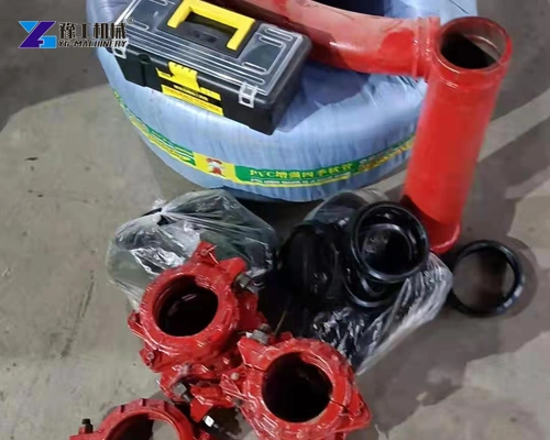
The actual distribution assembly, material pistons and wear parts, hydraulic filtration and cooling equipment, lubrication provision and compatible delivery components should be clear in the equipment scope.
Include the intended concrete, receiving sections, supply arrangement and drive preference in your enquiry. The equipment proposal should identify the actual machine and compatible conveying and service components.