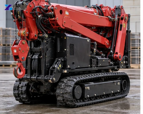
A tracked spider crane is a transport-and-setup decision as much as a lifting decision. Before comparing capacity, confirm the delivered envelope, route clearance, loading method, bearing surfaces, setup area and the load chart conditions that matter at the work point. A compact folded crane that reaches the site is useful; one that cannot be unloaded, leveled or deployed safely is not a commercial fit.
This guide is for a buyer preparing a shortlist or quotation. The YG figures are verified screening values, not a project approval or a substitute for the selected configuration’s load chart, ground review and site controls. Send drawings, photographs and measurements with the inquiry so the model recommendation reflects the actual route.
If the crane must pass through a gate, building or landscaped approach, send the narrowest point and route photos so the transport envelope can be reviewed first.
Start with the delivered transport envelope
Measure the route as a sequence, not as one doorway. Record gate width and height, turning clearances, overhead branches or beams, gradients, soft shoulders, floor transitions and the surface available for a trailer or ramp. Use the folded transport dimensions as the first filter, then allow practical clearance for steering, visibility and the person guiding the move. A nominal width that only fits when measured to the last millimetre is a procurement risk.
Mass changes the delivery plan. Check the crane mass against the trailer, ramp, unloading equipment and any temporary crossing. A route may accept the width but reject the wheel or track loading at a weak slab, drain cover or suspended floor. Ask the supplier to state which dimensions and mass belong to the transport condition and which accessories are separate.
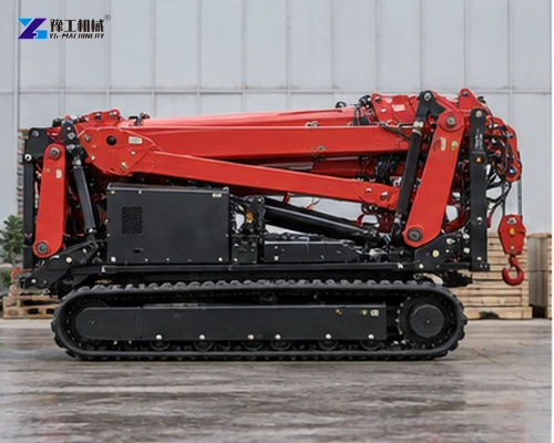
Survey the access route before choosing a model
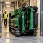
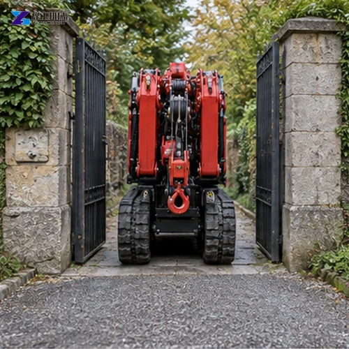
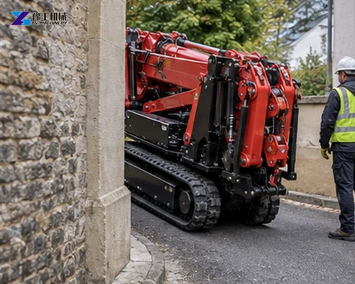
Walk the proposed path with a tape, laser or marked drawing. Measure the straight approach to each turn, because a machine can fit through a gate yet fail to align with the next opening. Photograph corners from the operator’s eye level and note whether the route is shared with pedestrians, vehicles or finished surfaces. Image3 shows the kind of narrow gate decision that should be verified before a purchase is approved.
Route information also affects unloading. Identify where the transport vehicle can stop, where ramps can be placed, and whether the crane must reverse, cross a threshold or travel over a protected floor. For a broader access comparison, the compact spider crane indoor lifting access guide helps frame the relationship between folded access and the later working footprint.
Use the transport table to narrow the shortlist
The table below keeps transport size, mass and lifting references together. Capacity alone is not a model-selection rule: the relevant row must also fit the delivery route and provide the required radius and hook height under the applicable load chart. All three references use a five-section pentagonal boom and list a travel reference of 0-2.5 km/h; neither is a promise of site productivity.
| Model | Capacity | Transport dimensions | Mass | Published lifting reference |
| YG-3 | 3 t | 2950 x 980 x 1560 mm | 2700 kg | 8.83 m maximum radius at 0.15 t; 9.9 m maximum hook height at 0.7 t |
| YG-5 | 5 t | 5000 x 1500 x 1900 mm | 6200 kg | 14 m maximum radius at 0.5 t; 16.8 m maximum hook height |
| YG-8 | 8 t | 5000 x 1600 x 2180 mm | 7200 kg | 16.5 m maximum radius; 18 m maximum hook height |
The YG-3 is the narrowest and lightest reference, but its radius example is paired with a 0.15 t load. The YG-5 and YG-8 provide larger published envelopes while imposing materially different transport and setup obligations. Compare the load position, radius, hook height and ground condition together; do not select from the maximum capacity label or infer a capacity at maximum radius.
For the operating side of the decision, read the spider crane lifting capacity and working-radius guide. It is useful for turning the required pick into a radius-and-load brief before a formal configuration is issued.
Share the load mass, pick radius, hook height and the tightest route dimension so YG can compare a compact model with the next practical alternative.
Plan loading, restraint and floor transitions
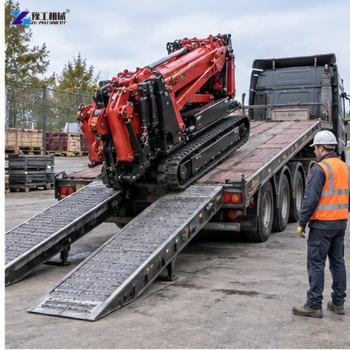
Loading is part of the equipment purchase. Confirm the trailer deck height, ramp length, ramp rating, approach angle and the equipment available to winch or guide the crane. Image4 shows a ramped loading operation; use it as a prompt to document who controls the movement, where the guide stands and how the machine is prevented from rolling or drifting.
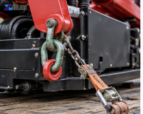
Ask for the transport restraint procedure and match it to the actual trailer. Image5 shows a close restraint point, but a photograph does not establish a permitted tie-down method. The quotation should identify the approved restraint locations and any protection required for hoses, boom sections, hooks and painted surfaces. Never improvise a tie-down from a convenient component.
Allow for unloading, setup and the working footprint
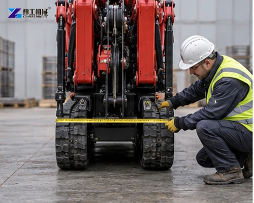
A folded envelope is only the delivery phase. After unloading, the crane needs room to position, deploy outriggers or supports, swing the boom and keep people outside the controlled zone. Image6 shows a width check on the folded machine; repeat the survey for the setup footprint and the route from the unloading point to the pick location.
Check slab condition, edges, drains, slopes and temporary mats before the machine arrives. Image7 illustrates a tight passage with a guide, but the final route plan should define communication, pedestrian segregation and the stopping points. If the route changes from hardstanding to a weaker surface, record the transition and obtain the supplier’s setup guidance rather than assuming tracked travel solves ground risk.
Send the unloading point, floor transitions, setup area and required lift position so the proposed crane can be checked beyond its folded dimensions.
Turn the lift into an acceptance-ready purchase
A useful quotation file contains the route drawing, narrowest clearance, delivered mass, unloading method, setup footprint, load mass, radius, hook height, ground notes and acceptance checks. Add photographs with a scale reference and identify whether dimensions are clear opening dimensions or wall-to-wall measurements. Ask the supplier to mark every assumption and every value that requires final site confirmation.
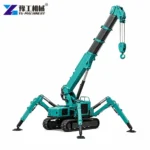
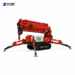
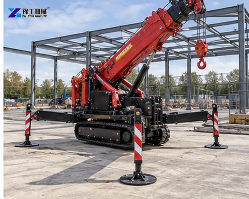
Before approval, verify that the selected model, boom arrangement and accessories match the intended lift. Confirm what arrives with the crane, what the buyer must provide, and how the machine will be inspected on arrival. Image8 shows the deployed crane on a prepared work surface: that is the end state the route and setup plan must support, not evidence that every site has the same working conditions.
Once the transport envelope, lift geometry and site checks are assembled, request a quotation that names the model, assumptions and required acceptance evidence.
Confirm the model against the complete route brief
A final model choice should survive two separate reviews: can it arrive, and can it perform the lift after arrival? Put the route dimensions beside the selected transport dimensions, then put the load, radius and hook height beside the applicable lifting references. This simple side-by-side check exposes a common mistake: choosing the smallest machine for access and discovering later that the pick geometry leaves no usable margin.
Use the tracked mini crane product range for family context, but keep the quotation tied to the verified model row and the buyer’s route evidence. Request written confirmation of unresolved dimensions, included accessories, setup assumptions and the acceptance record. That makes the commercial purchase reviewable by the project, logistics and lifting teams.
Tracked Spider Crane FAQ
No. The folded width is for route screening. Setup supports, boom movement, the load path and the controlled exclusion area require more space.
The YG-3 has the smallest listed transport envelope and lowest listed mass among these references. It still must satisfy the required load, radius, hook height and site conditions.
No. The published references pair capacity-related values with specific radii or hook heights. Use the selected configuration’s load chart for the actual pick.
Send clear opening width and height, turns, slopes, overhead obstructions, floor transitions, surface notes, unloading space and photographs with scale references.
Confirm trailer and ramp ratings, restraint release, stopping and communication arrangements, the unloading surface, travel path and the prepared setup area.
The machine must be positioned, supported and operated with room for the boom, load path, personnel controls and exclusion zone. A successful entry does not prove a safe lift.