
Horizontal directional drilling fluid is a designed construction system, not simply water added at the drill. It must help the tool cut, carry solids, cool and lubricate the string, support the bore and limit uncontrolled fluid loss. The required behavior changes with soil, groundwater, bore geometry, tooling and stage. A recipe copied from another crossing can fail even when pipe diameter and rig size look similar.
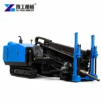
This guide organizes the buyer and project data needed to plan mixing, pumping, storage, returns and monitoring. It does not prescribe a universal formulation. Geotechnical, environmental and fluid specialists must approve the materials and trigger limits for the actual crossing. YG’s horizontal directional drilling equipment provides the rig envelope, while the HDD process guide retains the overall construction sequence.
Drilling Fluid Functions In Different Ground Conditions
List the strata along the planned profile, not only the material at the entry pit. Cohesive clay may create sticky cuttings and balling. Loose sand can require stronger bore support and careful return control. Gravel introduces large solids and loss paths; rock changes cutting size and cooling demand. Record groundwater, fill, utilities, fractures, previous excavations and any environmentally sensitive receptor.
Translate those conditions into functions that can be observed: tool cooling, cuttings suspension and transport, filter-cake or bore-wall support, lubrication, pressure control and separation. Some objectives conflict. Higher viscosity may improve carrying capacity but raise pumping losses and separation difficulty. The fluid program therefore states ranges, measurements and corrective actions rather than one fixed mix for the whole bore.
REVIEW MY GROUND AND BORE DATA
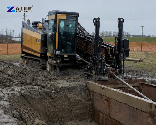
Building A Transparent Drilling Fluid Volume Balance
Estimate the drilled and reamed hole volume by stage, then add the circulation needed to transport cuttings and maintain returns. Include surface tank inventory, hose and drill-string volume, expected formation loss, cleaning losses, dilution, rainfall and contingency. Keep units consistent and show assumptions. The planned total is not the same as instantaneous pump flow, and theoretical annular volume is not the amount that must be purchased.
Compare pumped volume with measured returns during the work. A widening difference can indicate formation loss, storage in the bore, measurement error or an unintended release. Set reporting intervals and response thresholds before drilling. Inventory reconciliation also supports material purchasing, water supply, containment and disposal planning.
| Published HDD rig parameter | YG range used for preliminary planning | Fluid-system check |
| Maximum mud flow | 160–320 L/min | Verify the required operating point and pipe losses |
| Maximum mud pressure | 80–100 bar | Confirm hose, swivel and downhole component ratings |
| Pull/feed force | 160/100–320/320 kN | Coordinate tooling, bore cleaning and pullback plan |
| Maximum reaming diameter | 600–800 mm | Estimate cuttings volume and return capacity by pass |
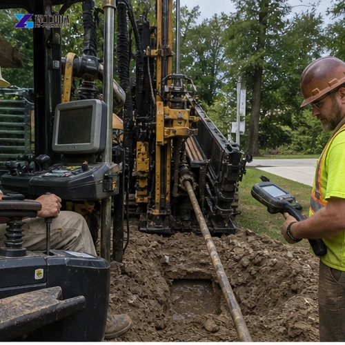
Drilling Fluid Mixing And Storage Capacity
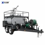
The mixing unit must hydrate and disperse approved products at the rate demanded by the rig without sending lumps or unstable fluid into the pump. Confirm clean-water quality and temperature, hopper and shear method, batch or continuous sequence, usable tank volume, agitation, transfer pumps and cleaning access. Provide separate space for fresh fluid, returns and waste so contamination is not hidden.
Match batch time to peak drilling demand and expected interruptions. A large tank cannot compensate for slow mixing, and high mixer output is wasted if storage, transfer hoses or the rig pump restrict delivery. Define who measures additions, how instruments are calibrated and how each batch is identified. Safe lifting, dust control and chemical handling follow the product safety data and local requirements.
Rig Pump Limits In The Fluid Plan
YG HDD models list maximum mud flow from 160 to 320 L/min and maximum mud pressure from 80 to 100 bar. These are machine envelopes, not instructions to operate at maximum values. The required point depends on nozzle area, drill-pipe losses, fluid properties, depth, tooling and annular condition. Verify pump curves and pressure ratings for hoses, swivel and downhole components.
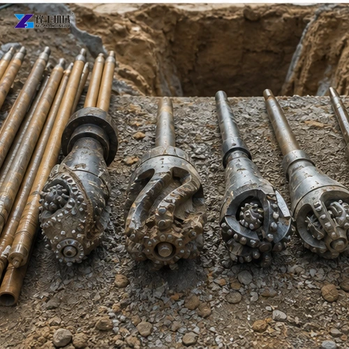
The same range includes pull/feed force from 160/100 to 320/320 kN and maximum reaming diameters from 600 to 800 mm. A larger reamer creates more cuttings and does not automatically receive enough effective cleaning because the rig has a higher force rating. Select tooling and passes with the fluid and return plan. Stop and investigate abnormal pressure instead of overcoming a blocked annulus by increasing pressure without authorization.
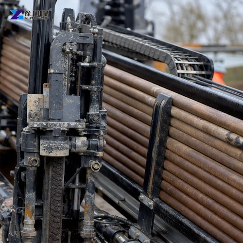
Containment, Cleaning And Reuse Of Drilling Fluid Returns
Map expected return points at entry, exit and intermediate risks. Provide lined pits or tanks, pumps, hoses, spill response, road protection and sufficient freeboard. Returns contain formation solids and may contain contaminants; characterize and manage them under the approved environmental plan. Do not assume every return can be recycled simply because it remains pumpable.
Screening, shakers, hydrocyclones or other cleaning stages must remove solids appropriate to the next use. Measure properties before reuse and account for dilution or treatment. Track recovered, reused and disposed volumes. Unexpected surface seepage or loss of returns follows a defined stop, locate, contain, notify and correct sequence rather than an improvised response.
Field Measurements Used For Drilling Decisions
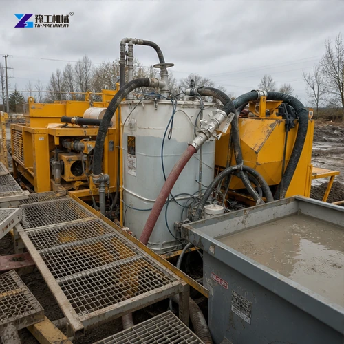
Use the measurements selected by the project fluid specialist, which may include density, viscosity, filtration behavior, sand content, pH or other properties. Record test method, instrument, sample location, time and drilling stage. A number without location and stage cannot explain what happened downhole. Trend pump flow and pressure, returns, torque, penetration and pullback behavior on the same timeline.
Create a trigger-action table. For each abnormal trend, state who is informed, what operation pauses, which checks follow and who approves restart. High pressure, lost returns, rapidly changing properties, excessive solids or poor hole cleaning require different responses. Keep retained samples where required and include disposal tickets and water records in the final bore file.
Fluid System Commissioning And Acceptance
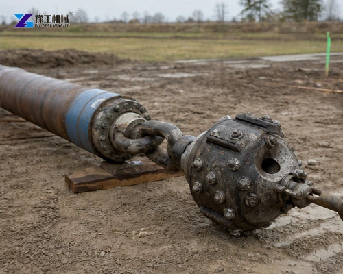
Before the main crossing, verify water supply, mixing sequence, tank circulation, transfer flow, pump controls, pressure protection, hose routing, containment and measuring equipment. A controlled circulation test can reveal leaks, dead zones and inaccurate level marks. Train the crew to use the same units and batch sheet.
During drilling, acceptance is based on the agreed bore and pipe result supported by traceable fluid records—not on consuming a planned number of bags. The final package should include ground assumptions, approved products, batch records, pumped and returned volumes, measured properties, incidents, corrections and disposal. Those records make the next bore decision more reliable and allow the equipment scope to be reviewed with evidence.
Horizontal Directional Drilling Fluid FAQ
No. Ground, groundwater, geometry, tooling, water quality and environmental constraints change the approved formulation.
Not automatically. Use the required operating point and verify pressure losses, nozzle area and component ratings.
Only after cleaning and testing show they remain suitable under the approved plan.
Provide the bore profile, soil report, pipe, tooling and reaming plan, water, site layout, return strategy, environmental rules and target schedule.
Please send your inquiry using the form below. YG will review the equipment envelope and identify information still required from the project specialists.