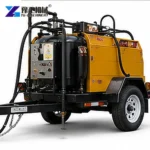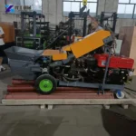
An asphalt crack sealing machine has to do two different jobs: keep a compatible sealing material ready for application and deliver it where the operator needs it. Gravity-feed and pump-fed machines organise the second job differently. That difference affects where the machine travels, how the operator follows the crack and which components need attention between applications.
This comparison focuses on the delivery arrangement rather than repeating a complete pavement-repair procedure. A well-prepared crack can still be awkward to fill if the outlet cannot follow its route. Equally, a longer hose brings little benefit if it adds handling and material-conditioning work that the task does not require. The useful choice connects the machine to the actual placement pattern.
Gravity Feed Keeps The Outlet Close To The Machine
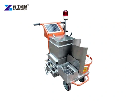
In a gravity-feed configuration, the height of liquid material above the outlet provides the pressure that drives discharge. Opening the valve lets heated material leave through the lower outlet without a delivery pump. As the level falls, that driving pressure changes; viscosity and valve opening also affect the stream. The machine generally travels close to the crack so its outlet can place material directly, keeping container, control and placement point together.
That simplicity changes the operator’s movement. The chassis, outlet and crack need to remain suitably aligned as work progresses. Narrow access, an irregular crack route or a difference in working level can make this less convenient than an open, accessible surface. The physical path for the wheels is therefore part of the equipment choice, not merely a transport detail.
Flow behaviour depends on the material condition as well as the outlet. Material that is too viscous for the selected arrangement may not flow consistently, while excessive opening can make precise placement difficult. The solution is to match the compatible material and machine controls to the task, not to treat additional heat as a universal way to increase delivery.
Consider whether the chassis can follow the crack route closely enough for direct placement.
Pump-And-Hose Delivery Separates Machine Position From Placement
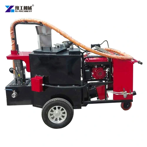
A pump moves the prepared sealing material through the delivery path to a hand-held outlet. This gives the operator more freedom to follow a crack while the main machine stays in a practical position nearby. It can be valuable where placement is intermittent, the crack changes direction or the chassis cannot conveniently follow every short section.
The pump, connections, hose and applicator create a longer delivery path than a direct outlet. The pump supplies pressure to move material through that path; hose length, internal size and viscosity influence resistance. Material can lose heat in the line even while the main container remains warm. Keeping the kettle at its operating temperature and maintaining suitable material condition in the hose are separate tasks. Heated hoses are a possible equipment feature, not something included on every pump-fed machine. The offered line arrangement must suit the material and duty.
Hose handling also deserves practical attention. An operator following a crack must be able to move without dragging the line across unsuitable edges or creating an obstruction for the crew. The useful reach is the reach that can be managed safely through the intended working positions, rather than simply the hose length printed on an offer.
Compare the applicator reach and the delivery path needed around the work area.
Asphalt Crack Sealing Machine Parameters
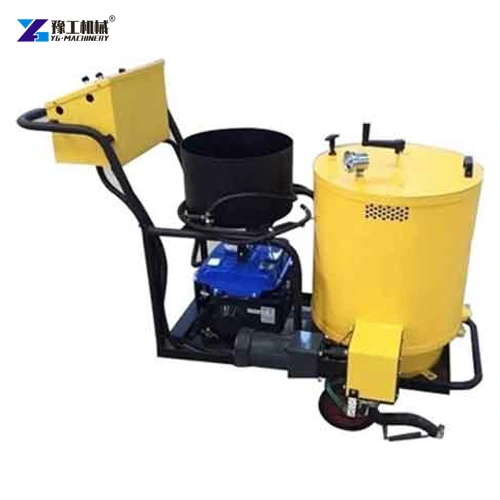
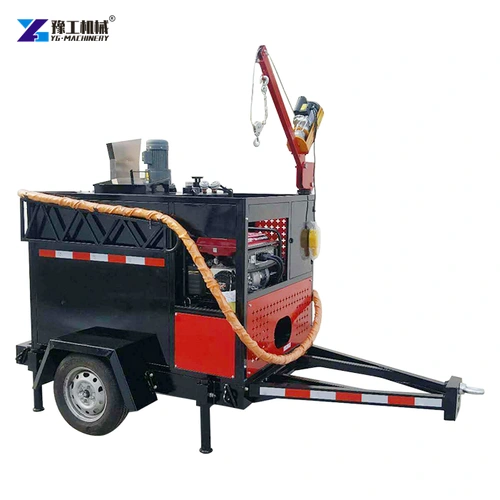
The YG-50L uses gravity discharge, while the YG-60L uses a pump to drive material from the container. Their heating arrangements differ as well. A hose-equipped application system extends that delivery path to a hand-held outlet, separating the placement point from the chassis. The separate hose-equipped machine shown in this article illustrates that arrangement; it is not identified as the YG-60L. For a YG-60L order, specify the outlet, hose and applicator package explicitly so that the quoted equipment matches the intended placement method.
| Parameter | YG-50L | YG-60L |
| Hopper volume | 50 L | 60 L |
| Discharge arrangement | Gravity feed | Asphalt pump feed |
| Heating arrangement | Liquefied gas | Liquefied gas with heat-transfer oil |
| Mixing arrangement | Manual | Manual |
| Travel arrangement | Push type with brake | Push type with brake |
| Published dimensions | 1,200 × 700 × 1,200 mm | 1,200 × 700 × 1,200 mm |
| Published machine weight | 120 kg | 120 kg |
Hopper volume helps describe batch size, while the delivery and heating arrangements describe how that batch reaches the crack. A larger container is not automatically a more precise applicator. The asphalt crack filling machine range provides the related product-family context.
The heater specification must also be separated from the sealant’s installation requirements. Heat-transfer oil carries heat indirectly around the material container; it does not establish that every sealant should be heated to the same setting. Use a compatible material and the actual machine and material instructions, including limits on reheating or prolonged holding.
Match the heating and delivery arrangement to your compatible sealing material.
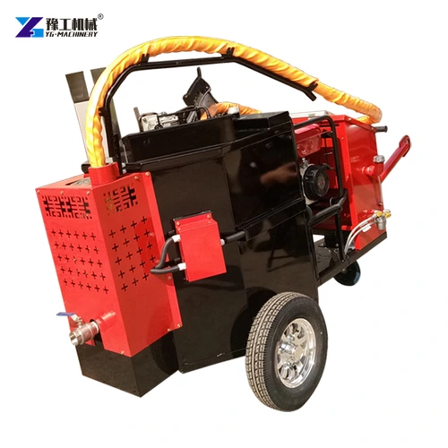
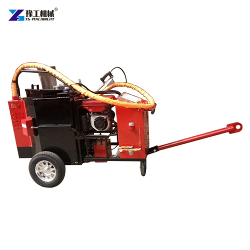
Four Placement Patterns That Change The Choice
- Accessible continuous cracks. Where the chassis can closely follow a clear route, gravity discharge can provide a direct relationship between machine movement and placement. The evaluation should include starts, stops and changes of direction rather than one straight demonstration.
- Short cracks spread around one working position. A pump-and-hose arrangement can let the applicator move between nearby sections without repositioning the entire machine each time. The benefit depends on how easily the hose can be managed between those sections.
- Work beside obstacles or restricted wheel access. A separate outlet can reach a placement point that the chassis cannot closely approach. The hose route and permitted machine position still need to suit the supplied equipment; reach is not a reason to obstruct traffic or work outside an agreed controlled area.
- Frequent pauses between applications. Stop-start work makes shut-off behaviour and the delivery path’s condition especially important. Assess restart consistency and the treatment of material remaining in the line under the manufacturer’s procedure.
These patterns explain why nominal filling speed is an incomplete buying criterion. A fast discharge system can spend much of the shift waiting for repositioning, hose handling or another crew operation. The best arrangement reduces the actual placement constraint instead of merely increasing a catalogue number.
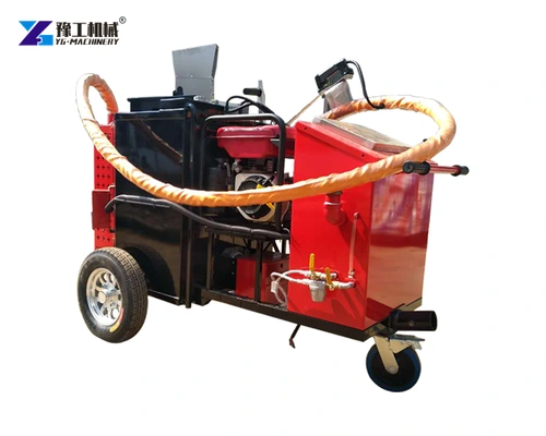
Inspect The Entire Delivery Path During A Demonstration
Watch the machine while material is being placed, stopped and restarted. The applicator should deliver a controllable stream without requiring the operator to repeatedly compensate for an unstable supply. Observe whether changes in position disturb the hose or outlet, and whether the crew can move through the intended route without repeated interruption.
For a gravity-fed machine, compare discharge with a fuller container and later in the batch, alongside outlet access and chassis movement. This reveals how changing liquid level affects the stream the operator controls. For a pump-fed machine, observe pump response, connections, hose support and applicator handling during placement and after an ordinary working pause. Evaluate the controls the crew will actually use instead of comparing only uninterrupted straight-line passes.
The demonstration should use the proposed compatible material, not an unidentified substitute chosen only because it flows easily. Evaluate the system under the placement pattern the buyer intends to repeat. This makes the result useful for selecting equipment without turning a single trial into a universal production guarantee.
Describe the material, placement pattern and access conditions for a defined machine proposal.
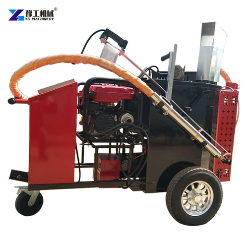
Servicing A Gravity Or Pump-Fed Crack Sealer
On a direct-outlet machine, buildup at the valve or nozzle can restrict the passage or prevent clean shut-off. On a pump-fed system, the pump inlet, connections and applicator also influence delivery. A narrowing outlet can cause an uneven stream even when the container is at the intended temperature. Inspect these locations under the supplied isolation and temperature procedure, never by reaching into a hot or pressurised material path.
Residual sealant needs the treatment specified for that material and machine. Water flushing, solvents and manual clearing are not interchangeable cleaning methods. Identify the approved end-of-shift treatment and permitted material holding or reheating limits when defining the equipment package.
A pump-fed machine adds service points associated with the pump and delivery line. Identify the relevant seals, connections, hose and applicator parts when defining the spare-parts package. Access should allow inspection and servicing after the machine has been safely isolated and the material system brought to the condition required by its instructions.
When buying an asphalt crack sealing machine, specify the delivery arrangement together with the compatible material, heating system and placement pattern. The quotation should identify the supplied outlet or hose package and service items. This is more useful than comparing hopper litres while leaving the operator’s actual delivery task undefined.
Asphalt Crack Sealing Machine FAQs
No. Pump feed provides a separate delivery path, while gravity feed can suit accessible work that the chassis can closely follow. The placement pattern determines the useful difference.
No. The delivery path must suit the material and the machine’s supplied arrangement. A hose does not by itself provide pumping or appropriate temperature management.
Not necessarily. Hopper volume describes the batch container. Outlet control, material condition, machine positioning and the delivery system determine placement behaviour.
Check controlled shut-off, consistent restart and the required treatment of material remaining in the delivery path, following the machine and sealant instructions.
Provide the compatible sealant, typical crack route, wheel-access restrictions, frequency of stops and the desired placement arrangement. These details help define the heating and delivery package.
Send the sealing material details, typical crack route and machine-access conditions to discuss a suitable heating and delivery configuration.