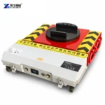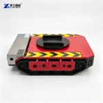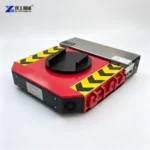
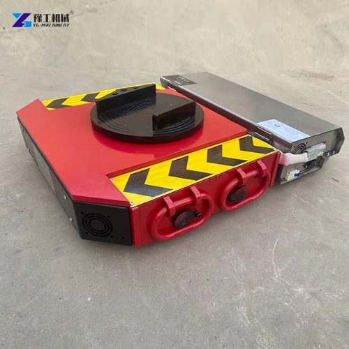
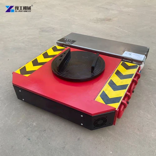
An electric tank trolley is a low-profile powered unit for moving supported machinery along a suitable floor. Here, the name refers to machinery-moving equipment, not a vehicle carrying a storage tank. Its upper pad bears part of the machine’s weight, while the battery-powered drive supplies horizontal movement.
The useful distinction is between carrying weight, generating travel and changing support height. The powered unit performs the first two; loading and unloading need equipment matched to the machine’s lifting provisions. Understanding that division makes it easier to choose the chassis, followers and controls as a working arrangement rather than a collection of accessories.
How an Electric Tank Trolley Supports and Moves Machinery
The trolley has a carrying path and a drive path. They work together during travel but answer different questions: how the machine’s weight reaches the floor, and how the supported load begins moving.
The carrying path starts where the upper pad meets an approved structural contact beneath the machine. Weight passes through the pad and chassis into the running gear and floor. A broad pad spreads contact over its own surface, but the machine base must still be suitable for the applied load. Nearby covers, trays and cable guards perform different functions.
In the drive path, the battery supplies electrical energy through the controller to the geared motors. The gearbox reduces motor speed and transmits turning effort to the driven running gear. Contact with the floor then produces travel force. YG lists two geared motors and a dual-channel driver for the configurations in the table; the supplied control arrangement determines which movement commands are available.
This explains why carrying capacity and drive power are both needed. A unit must support its assigned share of the machine and supply movement for the configured assembly. The required loading method is a further question: the powered travel mechanism does not itself establish a hydraulic lifting function.
Match the powered unit’s upper contact and mechanical arrangement to the machinery support task.
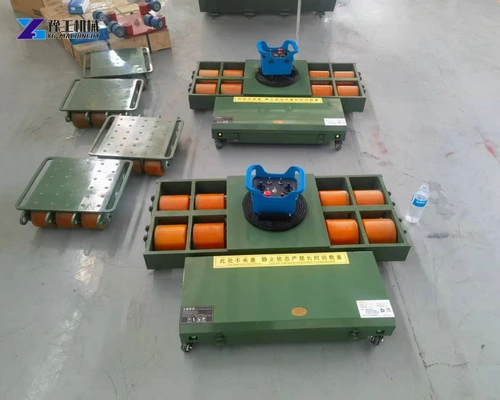
Loading and Unloading an Electric Tank Trolley
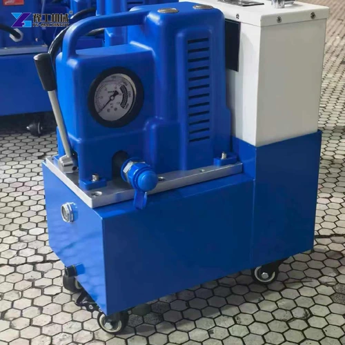
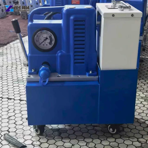
A floor-mounted machine must first transfer its weight from its existing supports to the moving units. Where the approved method uses hydraulic jacking equipment, the pump and jack supply the lifting movement; the trolley supplies horizontal travel after it has received its assigned load. These are separate functions with separate capacity and access requirements.
The roles can be distinguished as follows:
- Lifting equipment. A matched jack or cylinder acts at the machine’s designated lifting contact. Its capacity, stroke and connections belong to the lifting arrangement. The moving unit’s height determines how much insertion space that arrangement must provide, but is not a lifting stroke of the trolley itself.
- Moving supports. The trolley and any follower supports receive the machine at its permitted transport contacts. Their heights and contact geometry need to suit the loading clearance and the intended supported position. Compatible support heights keep the machine in its intended transport attitude, while each contact carries its assigned share of the load.
- Powered travel. After the machine rests on the suitable moving arrangement, the powered unit supplies the configured movement. The destination needs its own permitted unloading method to transfer weight off the skates again.
At the destination, the same division applies in reverse: the unloading equipment allows the machine to transfer onto the support needed for operation or storage, and the moving units are recovered. The machine’s handling provisions govern that transfer. This functional comparison identifies the equipment required without prescribing a jacking sequence or assuming that a transport support is suitable as a permanent machine foot.
Separate the lifting stage from horizontal transport when defining the required equipment.
Electric Tank Trolley Specifications
The following YG table describes named wheel-type powered moving units. Read powered-unit load capacity as the weight borne by the unit itself, separately from its towing designation. These values do not rate auxiliary pumps or other chassis variants shown in the product family.
| Parameter | YG 20T Configuration | YG 30T Configuration | YG 40T Configuration |
| Model designation | 20T | 30T | 40T |
| Towing weight | 20 metric tons | 30 metric tons | 40 metric tons |
| Powered-unit load capacity | 10 metric tons | 15 metric tons | 20 metric tons |
| Geared motors, with brakes | 750 W × 2 | 1,200 W × 2 | 1,500 W × 2 |
| Dual-channel driver | D2T80A | D2T100A | D2T200A |
| Listed remote-control options | C6/C7 or industrial remote | C7 remote | C6/C7 or industrial remote |
| Listed operating current | 60 A | 60 A | 120 A |
| Battery voltage and capacity | 48 V, 60 Ah | 48 V, 60 Ah | 48 V, 120 Ah |
| Battery options | Ternary lithium or lithium iron phosphate | Ternary lithium or lithium iron phosphate | Ternary lithium or lithium iron phosphate |
| External dimensions | 670 × 620 × 165 mm | 740 × 640 × 185 mm | 810 × 800 × 182 mm |
The 30T configuration lists a powered-unit carrying value of 15 metric tons. Each additional support needs its own suitable rating for the weight it carries. The distribution depends on the machine’s base and balance, rather than an automatic equal split.
For chassis fit, compare the available loading space with both the footprint and listed height. The 20T configuration is 165 mm high, while the 30T is 185 mm. A model with greater motor power may therefore require a different support arrangement. Battery and driver values identify the electrical package; runtime and any grade-related use need the selected system’s operating limits.
Compare the named model’s carrying value, drive package and dimensions with your application.
Matching the Electric Tank Trolley, Followers and Controls
The powered chassis, other rolling supports and operator controls perform different jobs within one move. A suitable comparison connects their specifications instead of choosing each item from its largest rating. Three relationships matter:
- Powered pad and follower contacts. The powered unit carries part of the machine while followers carry other portions. Their heights and upper contacts must suit the intended bearing areas. A taller powered chassis can change which supports receive weight, so replacing only the powered unit may require a revised support arrangement.
- Drive and steering behavior. Motor-driven travel must work with the rolling direction of the complete assembly. A follower that cannot follow the intended turn can resist movement despite having adequate carrying capacity. Establish the selected chassis and followers’ actual turning arrangement before comparing extra drive power.
- Control and battery system. The handset commands the functions supplied with that drive system. The battery chemistry, charging equipment and electrical connections must match it. An additional pack or controller is useful only when it is compatible with the ordered system; nominal voltage alone does not define compatibility.
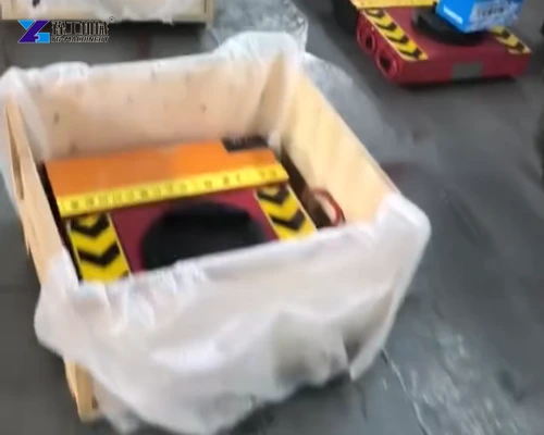
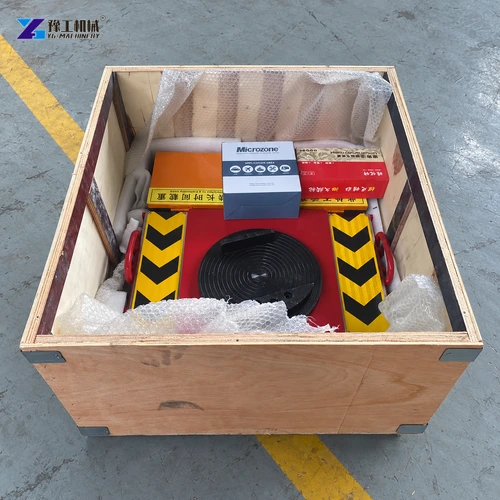
These relationships should be visible in the equipment schedule: identify the powered chassis, the followers intended to work with it, the matching handset and charger, and any independent lifting equipment. This keeps the supply boundary clear without confusing a compatible working system with a group of similarly sized parts. Any transport packing is a delivery provision, separate from the machine’s carrying and movement functions.
Identify the trolley, supports, controller, charger and any separate lifting equipment required in the delivery.
Electric Tank Trolley Applications in Machinery Installation
The trolley’s carrying-and-drive function is relevant to several ground-supported machinery tasks. In each, the benefit is powered movement between defined support positions; separate equipment provides any required initial lifting or final lowering.
- Moving a machine to its installation position. The trolley and followers carry the machine along the permitted floor route after it has been placed on suitable supports. The final position needs the specified permanent supports and a way to unload and recover the moving units.
- Repositioning equipment within a workshop. A machine may need to move between work areas rather than be lifted across an obstruction. Powered floor movement can be considered when the machine base, route and support arrangement suit that task. Turning requirements concern the entire supported machine, including its followers.
- Transferring supported equipment to a maintenance area. A suitable moving arrangement can deliver a secured assembly to its receiving support. The trolley provides transport; the maintenance fixture or stand provides the support required for servicing.
Before assigning the equipment to a machine, handover should confirm the actual controller functions, operating instructions, support arrangement and loading method. For a quotation through the YG equipment contact page, describe the machinery and its transfer between those two support positions. This connects the product specification with the work it must perform.
Electric Tank Trolley FAQs
No. The product name alone does not identify the running gear. The actual supplied construction and specification need to be checked; the wheel-type table must not be applied to a different chassis by appearance.
Do not assume it is. The configurations discussed here provide powered movement; no lifting stroke is established by the table. Separate jacking equipment may be required for the permitted loading and unloading method.
The listed 20T configuration has a towing weight of 20 metric tons and a powered-unit load capacity of 10 metric tons. The supported reaction must be evaluated against the carrying value, not the towing label.
Not automatically. They must match the supplied control and battery system. Similar appearance or nominal voltage does not establish electrical compatibility or identical operating functions.
Identify the powered unit, compatible follower supports, matching controller and charger, and any independent loading or unloading equipment. Each has a different function, so the proposal should show how the supplied items work together and which handling stages require separate equipment.
To enquire about an electric machinery-moving trolley, describe the machine and transport mass, approved support interfaces, required lifting arrangement and intended moving duty. Specify the powered unit and accessories separately so the proposed supply matches the job.