
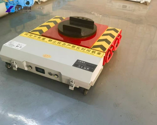
Battery powered machine skates move a supported mold between work areas without requiring people to supply the main pushing or pulling force. They are useful to consider where a toolroom needs repeated floor-level transfers between storage, maintenance and production. The battery powers the drive motors; the moving unit and accompanying supports carry the mold during travel.
The choice depends on the mold’s weight, its load-bearing base and the way it will be received at the destination. This article explains four mold-handling applications, then connects the YG specifications to support selection, intermittent battery use and unloading.
Battery Powered Machine Skates in Mold-Handling Applications
The same mold can make several different journeys during its working life. Battery powered machine skates provide the floor-moving part of those journeys; the equipment at each end depends on whether the mold is being stored, serviced or prepared for production.
- From mold storage to the toolroom. A mold retrieved from storage can be carried on its approved base to the preparation area. This separates the rack-handling task from the floor journey: suitable lifting equipment retrieves a high-level mold, while the skates move the supported assembly between areas. The transport base must keep the mold secured during that journey.
- To cleaning and repair stations. A mold may need to leave production for inspection, cleaning or repair and return afterward. The skates bring it to the maintenance station, where it transfers to the support intended for servicing. They transport the secured mold rather than acting as a fixture for opening it or working on its internal components.
- To a press-side staging position. The next mold can be brought to a designated position beside the production machine. This makes floor delivery a separate task from the subsequent mold change. Loading at machine height still needs the appropriate lifting, transfer deck or changing equipment.
- To a mold preheating station. A cold mold can be delivered to the station when its base and handling arrangement suit the moving supports. The station provides heating and its associated connections. Transporting a hot mold afterward is a separate temperature-related handling question, not a capability established by the skate’s carrying rating.
These applications share one requirement: the mold must rest on suitable moving supports before floor travel begins. Their differences lie mainly in retrieval and receiving equipment. Once those two ends of the journey are defined, the carrying capacity and size of the powered unit can be compared.
Describe the mold’s starting and receiving supports to discuss where powered rolling transport can fit.
Battery Powered Machine Skates Specifications
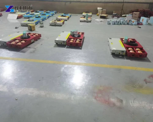
Read the YG table in two parts. Powered-unit load capacity is the weight borne by the powered unit itself. Towing weight describes the moving-duty designation of the powered arrangement; powered-unit load capacity describes the load on its own pad. In an arrangement with passive followers, the followers carry other portions of the mold while the powered unit supplies travel force. Selection therefore needs both the complete moving mass and the reaction borne by the powered pad, together with the permitted floor and operating conditions.
| Parameter | YG 20T Configuration | YG 30T Configuration | YG 40T Configuration |
| Model designation | 20T | 30T | 40T |
| Geared motors, with brakes | 750 W × 2 | 1,200 W × 2 | 1,500 W × 2 |
| Dual-channel driver | D2T80A | D2T100A | D2T200A |
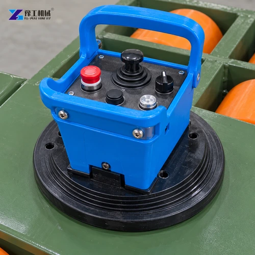
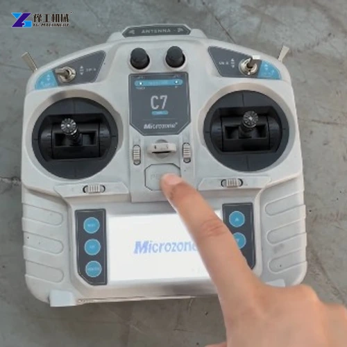
| Listed remote-control options | C6/C7 or industrial remote | C7 remote | C6/C7 or industrial remote |
| Listed operating current | 60 A | 60 A | 120 A |
| Battery voltage and capacity | 48 V, 60 Ah | 48 V, 60 Ah | 48 V, 120 Ah |
| Battery options | Ternary lithium or lithium iron phosphate | Ternary lithium or lithium iron phosphate | Ternary lithium or lithium iron phosphate |
| Towing weight | 20 metric tons | 30 metric tons | 40 metric tons |
| Powered-unit load capacity | 10 metric tons | 15 metric tons | 20 metric tons |
| External dimensions | 670 × 620 × 165 mm | 740 × 640 × 185 mm | 810 × 800 × 182 mm |
For example, the 20T configuration lists a towing weight of 20 metric tons and a powered-unit load capacity of 10 metric tons. If other supports carry the rest of a mold, each still needs an appropriate individual rating. Adding support ratings together does not show how the mold’s weight is actually shared.
The dimensions help determine whether the unit fits below the permitted mold-base contact. The 20T unit is listed at 165 mm high, compared with 185 mm for the 30T configuration. A change in model can therefore affect insertion space and the height needed at accompanying supports, not just motor power. Battery values are considered separately in the intermittent-duty section below.
Match the supported mold reaction and insertion space to a named YG configuration.
Mold Bases and Follower Skates for Powered Transport
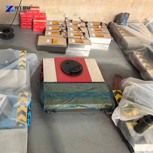
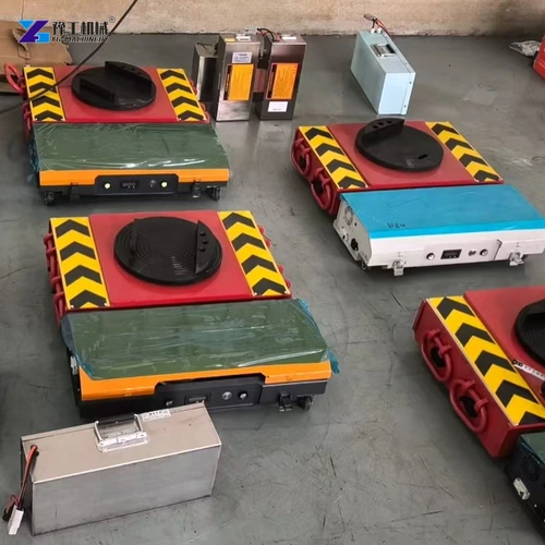
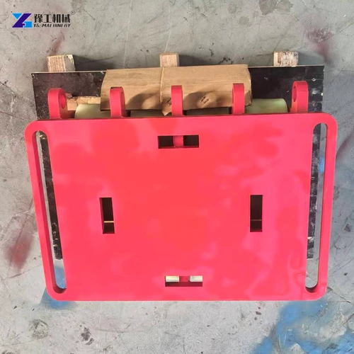
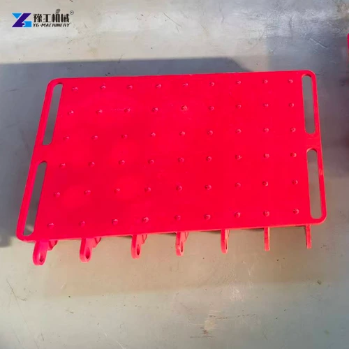
The mold base transfers weight into the moving equipment. A mold with designated bearing areas on its base plates presents a different interface from a mold secured on a purpose-designed transport carrier. In the first arrangement, the pads meet the mold’s permitted structural areas; in the second, the carrier must transfer the mold load into the moving supports. Cooling connections, guide components and covers remain clear of those bearing contacts.
Support selection then connects three mechanical details:
- Weight at each contact. A mold with an offset heavy section can place more weight on one support than another. Use the permitted transport orientation and load distribution rather than dividing total mass equally by the number of skates. Securing the mold sections also helps preserve that defined transport condition.
- Support height and contact shape. The powered pad and the other supports must meet the intended load-bearing areas at compatible heights. A pad that fits into a gap but touches only an unsuitable edge does not provide a satisfactory contact. Any carrier or load-spreading arrangement belongs in the approved handling design.
- Follower movement. Follower skates are the other rolling supports that carry the load without providing the powered unit’s drive. Their capacities, heights and running directions must suit the assembly. During a turn, a follower pointing against the intended path can resist movement even though its carrying rating is sufficient.
This explains why molds of equal mass can need different equipment arrangements. Weight establishes the carrying requirement; base shape and follower behavior establish how that capacity can actually be used. A mechanically suitable arrangement is also the basis for assessing battery demand.
Provide the permitted mold-base contacts to discuss compatible powered and follower supports.
Battery Powered Machine Skates for Intermittent Mold Transfers
Battery duty in a toolroom is usually better described as a sequence of moves and pauses than as a whole shift of continuous driving. A mold may be stationary during retrieval, inspection or receiving preparation. The powered travel between these activities is the part that draws on the drive system.
The 20T and 30T configurations both list a 48 V, 60 Ah battery option, but the 30T has a greater powered-unit carrying value and different motors. The larger model addresses a different supported load; sharing a battery specification does not make the two machines equivalent or establish the same number of loaded journeys. Compare carrying fit first, then evaluate the battery against the chosen model’s actual work cycle.
Consider two toolroom patterns. A mold delivered to one repair station may spend most of the elapsed period stationary while the work is done. A sequence of molds delivered to several press-side positions produces repeated loaded journeys, starts and turns during that same period. The second pattern keeps calling on the drive, whereas the first includes a long pause. Record movement time, maneuvering, load and charging opportunities separately; elapsed shift length hides these differences.
The charger must match the selected battery chemistry and electrical system. Follow the supplied charging and storage instructions during the pauses between tool changes. A removable pack or spare-battery arrangement should be included explicitly if required; nominal voltage alone does not establish interchangeability.
Describe loaded transfers and available charging intervals to compare the battery configuration.
Receiving and Unloading Molds After Powered Skate Transport
The receiving task determines how the mold leaves its moving supports. A repair stand must provide the support needed for servicing; a storage location must accept the secured mold in its storage condition; a press-side position stages it for subsequent loading. These are not interchangeable destinations simply because each can hold the same weight. Their bearing surfaces, working heights and access for the next operation can differ.
A floor-level staging position can keep the mold ready for a separate machine-loading operation. By contrast, receiving it on an elevated service stand adds a height change before it can be supported there. Identify which equipment makes that change and where the skates can be removed after weight transfers. This connects the transport purchase to the actual workstation without assigning a lifting or mold-insertion function to the powered chassis.
Keep the mold secured in its specified transport condition until the receiving support has taken over. Restoring production connections and preparing the tool for operation follow the mold-handling procedure. This makes the complete journey understandable: retrieve and load the mold, carry it between work areas, then transfer it to the support needed for the next operation.
For a mold-transport configuration enquiry, provide the mold’s transport mass, permitted base contacts and receiving arrangement. Those details connect the powered-unit specification to a workable mold journey.
Battery Powered Machine Skates FAQs
These skates provide floor-level rolling transport. Insertion into a press requires a suitable transfer interface and handling equipment; a rotating upper support does not establish height-adjustable or push-pull mold-changing functions.
The YG 20T configuration has a 10-metric-ton powered-unit load capacity and a 20-metric-ton towing weight. Match the actual supported reaction and complete support arrangement rather than treating towing weight as a single-pad rating.
The geometry determines where transport loads can enter the mold structure and whether supports fit beneath it. Projecting fittings or an unsupported plate edge should not be treated as structural contact areas.
Compare actual loaded movement, maneuvering and available charging intervals. Waiting during tool preparation differs from continuous travel, and the Ah figure alone cannot predict transfers per charge.
The complete arrangement still needs suitable support and a way to load and unload the mold. The powered chassis provides drive and carries its assigned reaction; other equipment must suit the remaining support and transfer functions.
For a mold-moving equipment quotation, include the tool’s transport mass and condition, permitted support locations, receiving height and expected transfer frequency. YG can assess the powered moving configuration against those interfaces.