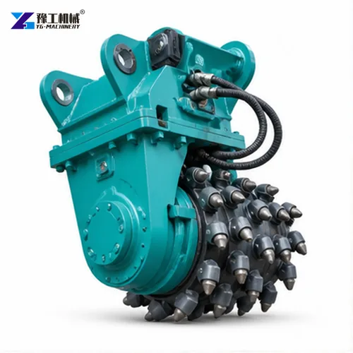
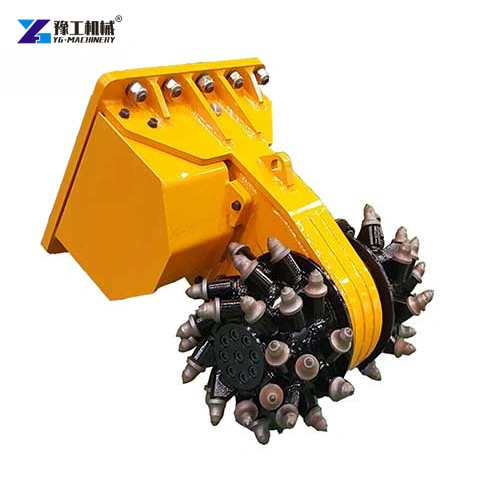
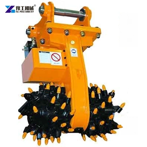
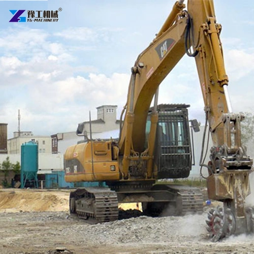
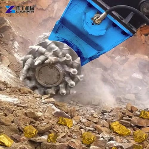
An excavator rock grinder is a drum-style hydraulic attachment that removes material through rotating cutting picks. Instead of striking one point like a breaker, it mills along a controlled path. That cutting action can be useful where the crew needs a shaped trench, a trimmed rock face or selective removal of concrete and asphalt rather than indiscriminate breakage.
YG lists the rotary drum cutter range as YG140, YG160, YG180 and YG240 for excavators from 5–10 t through 20–24 t. The attachment name may vary in search results—rock grinder, drum cutter or rock milling head—but selection should follow the listed model, work material and carrier compatibility, not the name alone. See the YG drum cutter product range for the attachment family.
How Does a Rotary Excavator Rock Grinder Remove Material?
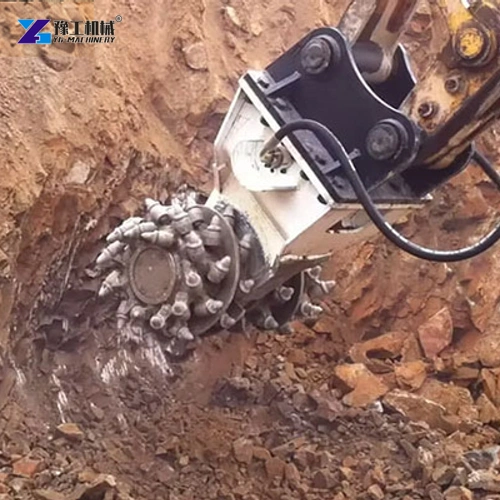
Hydraulic power turns the cutter drum, and the picks on its surface engage the material as the excavator positions and feeds the attachment. The operator advances the drum across a planned area in measured passes. The tool can therefore shape or reduce material along a line or surface, subject to the drum width, pick arrangement, carrier stability and material response.
A breaker concentrates impact at a chisel point, while a crusher bucket processes broken material in a bucket and a rotary grinder mills at the contact surface. These tools do not perform identical jobs. A grinder may help when the work needs a more controlled profile or gradual reduction, but it does not eliminate the need to handle the milled spoil or verify the required surface finish.
The rock grinder does not decide the finished geometry by itself. The operator follows a marked profile, controls depth and pass overlap, and checks the cut against the job requirement. Reinforcement, buried services, embedded metal, highly variable rock and restricted access can change the method or make another tool more appropriate.
Where Is an Excavator Rock Grinder Useful?
On utility and drainage work, a drum cutter can mill a controlled route through rock where a narrow cut is more useful than breaking a broad area. A crew can mark the required line, remove material in shallow passes and clear the spoil as the trench develops. The actual trench width and depth depend on the attachment configuration and ground, so the excavation plan—not the generic tool name—sets the target.
Tunnel and underground work may use a drum cutter to trim a contour or remove local overbreak material. In a tunnel profile, gradual cutting can help the operator follow a surveyed line; however, tunnel support, dust, ventilation and the approved excavation method remain the controlling site requirements. The attachment should not be described as a substitute for geotechnical design or a tunnel safety plan.
The same milling principle can be applied to selective concrete removal, bridge-deck cleanup or asphalt surface work when the tool and carrier are configured for the material. These are different tasks: concrete may contain reinforcement, pavement may have layered construction, and a tunnel face may have variable rock. Inspect a representative area and agree on the desired cut and spoil handling before scaling the method.
- Rock trenching for utility, drainage or service routes.
- Local profile trimming in tunnels and underground excavation.
- Selective milling or removal on concrete, bridge-deck and asphalt work where the configuration is suitable.
The material and required cut shape determine whether rotary milling is the right tool. Compare the job against the attachment’s carrier class and published dimensions before choosing a drum cutter.
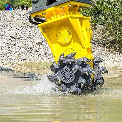
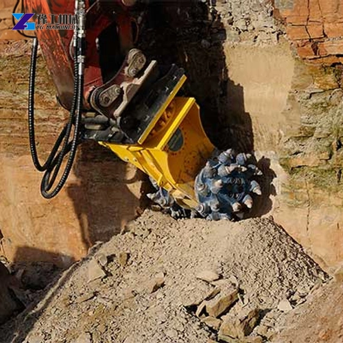
YG140–YG240 Excavator Rock Grinder Parameters
These are four separate model configurations. The excavator-weight bands help identify the intended carrier class, but they do not replace checks of the carrier’s hydraulic system, mounting, auxiliary circuit and operating limits.
| Parameter | YG140 | YG160 | YG180 | YG240 |
| Excavator weight | 5–10 t | 10–15 t | 15–21 t | 20–24 t |
| H × W × D | 650 × 410 × 390 mm | 820 × 650 × 460 mm | 830 × 780 × 480 mm | 1,395 × 960 × 620 mm |
| Maximum power | 22 kW | 45 kW | 55 kW | 65 kW |
| Rotation speed | 0–120 r/min | 0–100 r/min | 0–80 r/min | 0–90 r/min |
| Hydraulic flow (as printed) | 40 L/min | 100–110 L/min | 130–180 r/min | 200–250 r/min |
| Maximum torque | 3,200 Nm | 5,400 Nm | 5,600 Nm | 12,800 Nm |
The published hydraulic-flow units for YG180 and YG240 are printed as r/min, unlike the L/min values on YG140 and YG160. That is an apparent unit inconsistency in the listed data. It is preserved here rather than guessed or silently corrected; obtain a written confirmation of the required flow before matching either model to a carrier.
The excavator weight range is a screening value, not proof that every excavator in that weight class can power the attachment. Confirm hydraulic pressure and flow, return-line requirements, mounting and auxiliary controls with the exact carrier and model. A mismatch can prevent the drum from operating within its intended conditions or can overload the carrier circuit.
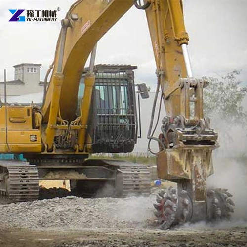
Set the Cut by Material, Pass Depth and Spoil Removal
Begin by identifying what is in the cutting path: intact rock, fractured rock, concrete, asphalt or mixed material. The pick contact and tool wear depend on the material and its condition. If reinforcement or a buried utility is possible, verify its location before milling. A small trial cut can reveal whether the drum can follow the required profile and whether the removed material can be cleared at the same pace.
Use a marked line and shallow initial pass to check the cut width, edge condition and excavator stability. Measure the result rather than relying on a visual estimate from the cab. If the profile is too wide or the surface is irregular, adjust the pass path and overlap only within the equipment’s operating guidance. Avoid claiming a universal depth-per-pass or hourly output: geology, pick condition, carrier hydraulics and operator technique change the result.
Material removal is only one part of the cycle. The work area needs room to collect, load or otherwise manage spoil without forcing the carrier to cross the newly milled surface repeatedly. In trenching, the sequence of cutting and clearing affects access; in a tunnel or on a deck, dust control and surface inspection also belong in the method.
Send the excavator make and model, auxiliary flow confirmation, material, cut profile and working environment for a model-specific compatibility review.
Excavator Rock Grinder FAQs
No. A rotary grinder removes material with a rotating drum and cutting picks, while a breaker uses impact through a chisel. The better choice depends on the required cut shape, material, access and spoil handling.
The product family is presented for rock and for selected concrete and asphalt milling or trimming tasks. Material condition, reinforcement, pick configuration and carrier compatibility must be checked for the actual job.
The published bands are 5–10 t for YG140, 10–15 t for YG160, 15–21 t for YG180 and 20–24 t for YG240. Hydraulic and mounting requirements must also match.
Not safely from the table as printed: YG180 is shown as 130–180 r/min in the flow field. Ask YG to confirm the required hydraulic-flow unit and value in writing before selecting or setting the carrier circuit.
No. Rotation speed is a specification, not an output promise. Material hardness, pick wear, pass depth, carrier hydraulics, operator method and spoil removal all affect the work rate.
Use the Drum for the Cut the Job Actually Needs
A rotary excavator rock grinder is most useful when the work benefits from controlled milling along a planned profile. Match the YG140–YG240 model to the excavator and verify the hydraulic figures—especially the YG180 and YG240 flow units—before approving the setup.
For a compatibility check, provide the excavator model, intended material, cut dimensions and confirmed hydraulic data.