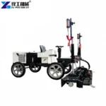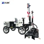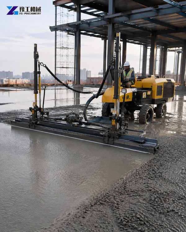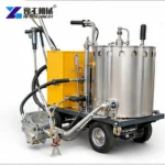
A laser screed working between columns has to fit a sequence of concrete placements, not merely a rectangle on a drawing. Its leveling head must reach the wet concrete, the chassis must occupy an appropriate working position, and the crew must finish the areas that the machine cannot reach. A wider head can cover an open bay efficiently but become awkward where a column interrupts the pass. A telescopic machine can reach away from its chassis, but that reach is useful only when the head has an unobstructed path.
For an industrial floor with repeated column bays, compare the placement strips and machine movements before comparing nominal output. The decisive question is whether each configuration can complete useful passes and move to the next working position without creating inaccessible pockets or interrupting concrete supply.
Laser Screed Head Width And Chassis Clearance
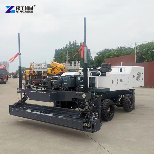
The leveling head contacts the concrete across its working width. The chassis supports and positions that head. These two widths are not interchangeable: a machine can have enough room to travel along an access route yet lack room to align its head for a complete pass between obstructions. Conversely, the head may reach across a strip while the chassis remains in a separate working area.
On the floor plan, identify the head path and chassis position separately. Include the column face, protective kerbs, temporary formwork and equipment that will actually be present during the pour. Nominal column spacing is not the clear width available to the machine. The connection between bays matters too; a suitable straight pass does not establish that the whole machine can turn and approach the next strip.
This distinction also explains why a head-width figure cannot supply a turning radius. Turning depends on the machine geometry, steering arrangement and the position of the head. Obtain the relevant transport and operating dimensions for the offered configuration instead of treating its leveling width as its entire footprint.
Compare the head path and chassis clearance for your column layout.
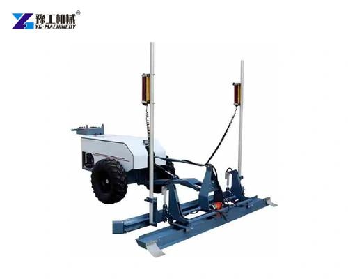
YG Laser Screed Parameters
| Parameter | YG-CL300 | YG-CL300A | YG-ZP30 | YG-ZP40 |
| Leveling width | 2,500 mm | 3,000 mm | 3,100 mm | 4,000 mm |
| Listed leveling thickness | 60–300 mm | 60–300 mm | 100–450 mm | 100–500 mm |
| Telescopic arm | Not listed | Not listed | Listed | Listed |
| Listed telescopic length | Not listed | Not listed | 6,000 mm | 6,000 mm |
| Machine weight | 1,000 kg | 1,000 kg | 5,500 kg | 5,500 kg |
The CL300 and CL300A offer different head widths within the lighter listed configurations. The ZP30 and ZP40 add a telescopic arrangement with different head widths and greater machine weight. Those differences change how the equipment is positioned and moved; they do not establish that the larger machine is preferable for every industrial floor.
The thickness range describes the listed machine application range, not approval of the slab design. Reinforcement, specified slab thickness, concrete properties and the construction method remain project requirements. Likewise, a 6 m telescopic length is a machine specification, not a promise that every point within a 6 m circle can be finished around columns.
Match a head width and machine arrangement to the placement strips.
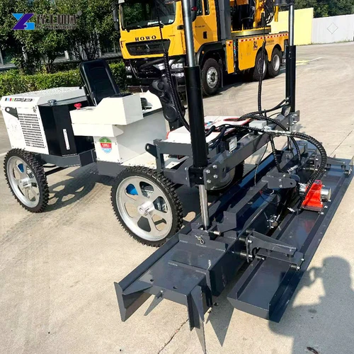
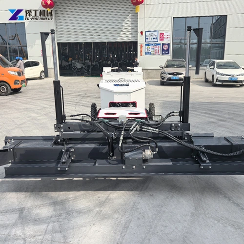
Four Working Areas In A Column-Bay Concrete Pour
- The open central strip. A wider head may reduce the number of adjacent passes where concrete and machine access are continuous. Its benefit is greatest when the full working width can be used rather than repeatedly interrupted by obstacles.
- The approach beside a column. The head must approach without its frame, receivers or supporting structure contacting the column. Compare the physical head assembly, not only the nominal strip of concrete it levels.
- The connection to the next bay. The chassis needs a workable route for repositioning. A pour sequence that leaves a machine trapped behind completed or newly placed concrete can cancel the advantage of a fast central pass.
- The perimeter and isolated pockets. Edges, column surrounds and narrow returns may need separate screeding and finishing methods. Identify these areas before the pour so that machine leveling and local finishing join at the required elevation.
These four areas should be considered as one placement sequence. Choosing the machine for the largest open strip alone can leave the crew with a disproportionate amount of interrupted work elsewhere. Choosing solely for the narrowest pocket can also sacrifice useful coverage in the main floor area. The better comparison accounts for the actual balance of open and obstructed work.
Show the open strips and restricted pockets in the proposed pour.
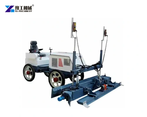
Telescopic Laser Screed Reach Between Columns
A telescopic arm lets the head work away from the chassis. This can allow useful passes from a defined machine position where the placement layout and supporting surface permit it. The crew still needs to consider how the arm extends and retracts and where the head travels throughout that movement.
A column blocks a physical path even when its surrounding concrete lies within the nominal reach. Check the approach from the intended machine position and the return movement after the pass. Relocating the chassis may create a usable path, but relocation takes space and time and must fit the placement sequence.
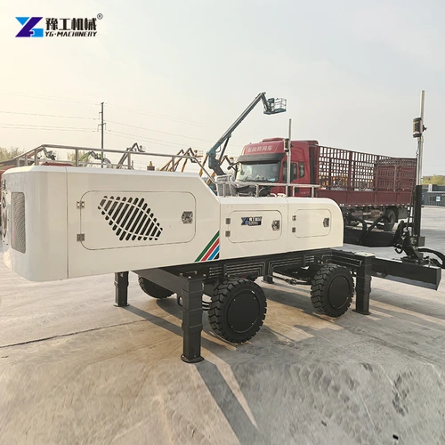
The heavier listed telescopic machines also require a different handling and support assessment from the lighter configurations. Machine weight is not a floor-pressure calculation. Wheel positions, contact areas and the relevant ground or slab condition must be assessed for the actual setup. Do not infer permission to travel on a surface from the screed-head dimensions.
The practical advantage is separating the machine’s standing position from the strip being leveled. In an open bay, a suitable telescopic arrangement can work a strip while the chassis stays in its planned position. Beside a column, that same extension may bring the head or arm into the obstruction, so the next strip needs a different approach or a chassis move. The useful comparison is the number of complete, unobstructed passes available from each position—not arm length by itself.
Review the intended machine position and the clear extension path.
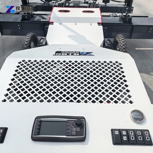
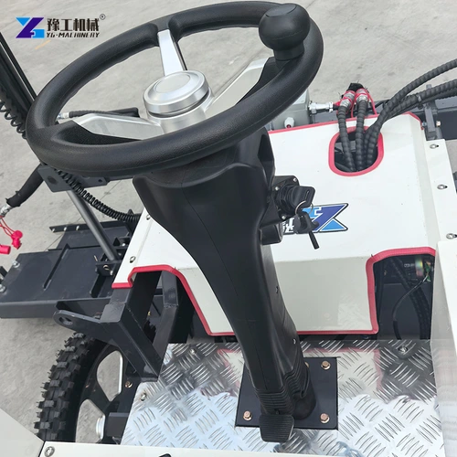
Laser Screed Level Control And Column-Edge Finishing
Three operations need to be kept distinct when planning the floor:
- Machine screeding brings accessible fresh concrete to the specified level with the working head.
- Local screeding brings restricted patches beside columns and edges to the same reference where the machine head cannot make a complete pass.
- Surface finishing develops the required surface after placement and screeding, using the specified methods and timing. Depending on the floor, this can include floating or trowelling; it is a different task from setting the concrete’s elevation.
This distinction explains why machine access and finishing access are both needed. A strip may be level while its surface still needs further work, and a neatly finished column surround can still be too high or too low relative to the adjacent floor.
Laser control provides an elevation reference through the transmitter, receiver and machine control system. It does not make a receiver effective when the required signal is obstructed. The transmitter position and the receiver’s visibility through the planned passes therefore belong in the setup review, especially where columns and temporary equipment interrupt sight lines.
The transmitter establishes the reference plane. Receivers on the screeding assembly detect its position relative to that reference, and the control system uses the signal to correct the working head’s elevation. This is the connection between the laser reference and the concrete surface: the head works to a controlled level while the operator manages its path and the crew supplies concrete. Laser control does not steer the head around a column or move surplus concrete into an inaccessible corner.
Locally screeded concrete around columns must meet the level of the adjacent machine-screeded strip. A shared elevation reference and the specified checking method keep that transition consistent. Too much material left at the junction can create a high ridge; an underfilled patch can leave a depression.
Work that junction while the adjacent concrete remains suitable for the planned operation, then carry out the required surface finishing and level checks. A smooth-looking join is not a substitute for the floor’s specified acceptance checks, and a machine pass does not complete every subsequent finishing operation. The laser reference, local screeding and later finishing are connected stages, with the level established before the required surface is completed.
For a large unobstructed bay, head coverage and concrete supply may dominate the choice. For a closely spaced column layout, useful approach directions and the share of local finishing can be more important. The concrete floor leveling machine range provides the related equipment overview; choose the arrangement that can follow the complete placement sequence.
A useful equipment trial follows a representative bay, including a column approach, a change of position and a locally finished edge. Compare the complete sequence rather than timing only one unobstructed pass. This reveals whether head width, reach, repositioning or local finishing is the practical constraint.
Laser Screed Selection FAQs
No. The physical head assembly, its approach angle, the chassis and working clearances must fit. A nominal leveling width is not an installation-clearance specification.
Only if there is a clear physical path from a suitable machine position. Reach does not remove obstructions or establish access from every direction.
A wider or longer-reaching machine is useful where it can complete longer open passes from suitable positions. A more restricted floor can favour a different arrangement with easier repositioning. Compare usable passes, support conditions and the amount of local finishing alongside machine weight.
Restricted column surrounds can require local screeding to the same elevation reference as the machine-worked strip. Plan access to the patch, the junction with the adjacent concrete and the subsequent surface-finishing operation before the pour.
Screeding establishes the level and profile of the fresh concrete. The required surface texture and finish are developed through the subsequent specified operations. Include both the machine-worked strip and a locally screeded column edge when evaluating how those stages connect.
For a configuration review, send the bay layout, placement-strip widths, access route and required local finishing arrangement.